Speak And Spell Part 1 – Set-up and First Glitch

Kill Switch, Output, Glitch, Speak And Spell

Today I wanted to show you guys another circuit bending job I’ve been working on that I’m pretty exited about. I found a working Speak And Spell at a local Value Village recently and have begun exploring and cannibalizing its innards for my own amusement. If you’ve so much as googled circuit bending you are likely familiar with the speak and spell and what it’s capable of (not to mention its sister devices the Speak And Read and Speak And Math), These devices can be turned into incredibly effective electronic instruments. I have never worked with one before but I wanted to take you guys along with me for the ride and share with you my victories and mistakes as we turn this device into something awesome.

If your looking for in depth schematics and diagrams of the circuit and possible bends, Casper Electronics offers a lot of great information.

Kill Switch And Output

circuit bending

The first thing I did to prepare the device for bending was to add a kill switch along the power connection and a switched output jack from the speaker connection. As these modifications are identical to what I did on my Vtech Alphabet Apple I will not go into to much detail here. Note the Speak and Spell does feature an on board headphone jack which could be used in place of the output jack it you prefer but I like having 1/4 inch jacks on all of my devices so I added one anyway.

The First Glitch

Speak And Spell - Glitch 1

Next up was to start exploring the circuit, I began triggering sounds from the keypad while touching a pair of probes to different pins on the board. After a little bit of searching I had come up with one which spewed bits of gibberish or random tones when the points were touched. I attached two lengths of wire and experimented with a few different control methods before settling on attaching them with a button.

A Silly Mistake

Speak And Spell - Mistake

Those of you who have worked with Speak And Spells before may have already noticed it but I made rookie error with my first glitch. I am slightly embarrassed about it but wanted to share it as a cautionary tale. When choosing the location of the button I began drilling from the back thinking that I was clear of the keypad, but in my excitement I did not check to see how far clear of it I was. Sadly the hole I drilled damaged the key matrix and has stopped many of the keys on the left side of the keypad from working. Luckily, enough keys still work that I can still turn the device on and trigger lots of noises but it has interrupted normal function of the device. No more scary robot hangman for me…

Salvaging Parts – Sears Clock Radio

sears clock radio - LXIEver since I started working with electronics it seems like I have a never ending flow of random electronics appearing in my workshop. Abandoned stereos and radios, Retro toys, Clocks, Printers, you name it. But what to do with all these broken down wrecks? In some cases if the devices are still in some kind of working order they can be hacked, repaired or circuit bent into usable order (either for their original purpose or some new one) but in the case of a device which is broken beyond usefulness such as this LXI series Sears brand clock radio I turn to salvage.

There are a host of excellent reasons for salvaging parts from old broken electronics. It is an excellent way to fill out your parts library and can often provide you with unique or interesting components you would not normally buy (or even be able to find in some cases). Also it can really help clear out rubble both in your work space and in local landfills. Instead of a shelf full of old stereos you could break them down, remove the casings and reduce them to a box or two of components. Further taking apart a device piece by piece can give you untold insights into how it was manufactured and how it works, you can learn vast amounts and sometimes interesting new tricks.

What to Salvage

Similar to choosing a circuit bending victim the ideal candidates for salvage are made before the year 2000 as generally items made after this point are almost entirely made up of surface mount components. Generally speaking the older the device the better, just make sure you aren’t ripping apart a valuable antique. As far as what types of devices to cannibalize, It really depends on the type of work you are doing. Since most of my projects work with sound synthesis and amplification I typically go after audio equipment like old stereo systems, radios, mixers, amplifiers, guitar pedals and so on. If you have a different focus though other items may be more useful tho. For instance if you are interested in robotics printers have an excellent array of motors and gearboxes ripe for the picking. The more you open things up the better a sense you will get for which devices are going to be rewarding for you and which are best left alone, as with most things the best way to learn is to start opening things up.

Lets Get Started

Make sure before you start tearing anything apart make sure the device is unplugged and all batteries are removed

LXI Sears Clock Radio - Case Removed

Removing the case from a device for the first time is like unwrapping a present, I usually spend some time after doing so to look over the device and see what parts I’m most interested in, already I can see there’s a good sized speaker on the left side, a couple interesting potentiometers and switches, and a host of trim pots, resistors, diodes, transistors and caps. There are also a few stranger radio parts connected to the tuner which have peaked my curiosity.

LXI Sears Clock Radio - Speaker and transformerBefore I get to deep I remove any parts which hang from the board such as the speaker, transformer and any battery clips to free the circuitry entirely from the casing. I discard the casing and begin removing any other mechanical or supplementary parts.

LXI Sears Clock Radio - Cassette Deck and TunerPictured above are the mechanical parts from the tape deck and tuner, I was able to get some good gears and a working motor from the tape deck. I’ve left the pulley system from the tuner intact as I feel I may be able to re purpose it down the road as a fine tuning knob for a potentiometer.

LXI Sears Clock Radio - BoardOnce you’ve got the main circuit board by itself you can begin de-soldering components using a soldering gun and a solder sucker or wick. Typically at this point I will add the circuit board to my “Board Bin” and remove the components as I need them but if you prefer or if there are specific components you are most interested in you can take them off immediately. Remember to test all components before using them elsewhere as sometimes certain parts will breakdown over time or through abuse the device may have taken in it’s lifetime.

5 Tools To Stay Organized

I’m working away on some exiting new projects but until I get them finished I wanted to share some quick ways that I use to keep my workstation organized. With thousands of small parts, endless types and colors of cable and a pile of specialized tools it can be very easy to watch your workstation descend into chaos. Today I’ll go over a few quick tips to help you keep things organized so you can spend less time searching for tools and parts and more time focusing on your builds.

1 – Component Shelves

Component Shelf

Component shelves can be purchased online from amazon or at most major hardware stores and I honestly can’t imagine my work area without them. I’d recommend purchasing a few of these as soon as you start exploring electronics, set up a sorting system and keep to it. This way instead of digging through a pile consisting of every resistor you own you can just reach out and grab it from the corresponding drawer.

2 – Wire Rack

Wire Rack

It doesn’t take long for your spools of wire to start unwinding and trailing around your workstation, the simple solution to this is to set up some kind of wire rack and place the spools onto it, this way you roll and unroll them with ease. There are commercially available wire racks though the one I use is actually an old broken lamp. Paper towel racks are also often very effective.

3 – Bins

Bins

For parts or devices too large for your component drawer I keep a number of bins of various sizes on selves around my workstation, Label each bin and sort items into them as necessary. I have large bins for things like cables, toys and “Devices for Salvage” then there are smaller bins for things like adapters, alligator clips and speakers.

4 – Tool Baskets

Basket

I keep a few baskets around my workstation which are where I store all of the common tools I use on a day to day basis so that they are at hand whenever I need them. In these baskets you can find things like pliers, wire strippers, angle cutters, a few screwdrivers and my solder remover.

5 – Small Containers

Containers

Small containers are great for holding all the hundreds of tiny screws you remove from devices as you take them apart, along with any other small parts that you remove and don’t want to lose. Typically I get these from dollar stores though daily dosage containers from pharmacies are excellent as well.


Awesome LEDs

Vtech LEDs

Whether its a circuit bent monstrosity or a simple oscillator, nothing brings a project to life quite like a couple LEDs. Today I wanted to show you an easy trick I picked up from a friend to give the LEDs you add to your projects a clean and professional look without having to spring for fancy lights or sleeves. All you need is some hot glue, a shallow nut or washer and some electric tape.

Start out by drilling a hole where you want the LED to be, This hole should be bigger than the LED itself and around the same size or slightly larger than the hole in your nut or washer. Once the hole is drilled line the washer or nut up with it and place a piece of electric tape over it. Take a moment to ensure the electric tape is taught and smooth over the hole in the nut and that it did not move when you were taping it down (It should still be lined up with the hole in your project).

Next we want to turn over or open up the device and pour a generous amount of hot glue into the hole from the back, allow it to heap up a bit on the inside of your device, before the glue has a chance to solidify push the LED into the hot glue, do your best to stop it just shy of pressing into the tape on the other side so there is still some glue between it and the tape. Once it is in place allow the glue to dry for a few moments, If you would like you can take this opportunity to wire the LED to the circuit (If you haven’t already)

Once the glue has completely dried gently remove the tape, You may need to use an Exacto knife to remove any excess glue leaving a smooth surface filling the hole in the nut. Since the glue is translucent when the light is turned on the entire hot glue plug will glow giving the appearance of a large flat bulb.


VTech Apple Part 4 – Body Contacts

circuit bending vtech appleThe next stop on our circuit bending exploration of the Vtech Apple is going to be to add some body contacts. I really love body contacts as a control method as you can get a lot of range and really interesting tremolo effects with very little effort. The bend I’ll be adding them to is a second pitch modification I found while exploring the circuit. Oddly enough this bend seems to change between modifying the pitch up and down dependent on which mode the toy is set to (using the worm on the right side), On the modes where it lowers the pitch you can get extremely low droning noises using the body contacts which I’ve been really enjoying.

VTech Apple Part 1 – Kill Switch and Line Out

Vtech Apple Part 2 – Exploration and Pitch Adjustment

Vtech Apple Part 3 – Voltage Starve

Vtech Apple Part 5 – 555 Trigger Oscillator

Vtech Apple - Body Contacts CircuitThe above photo shows the two solder points on the board I used to produce these effects, Once I had attached the wires I experimented with a number of different control methods and components including potentiometers, resistors with switches and buttons, and even strings of capacitors and LEDs (too see what would happen). I was able to create a number of strange effects but the one I found most interesting and which worked most consistently was body contacts.

Once I’d settled on a control method I drilled holes in the case and threaded 2 screws through them. Though I used screws on this project there are really limitless materials you can use to create body contacts. Any conductive piece of metal should work so it is really a matter of taste. Some examples I have seen used include thumb tacks, guitar strings, conductive tape, pennies or nuts and bolts, the possibilities are endless.

Vtech Apple - Body ContactsOnce you have the screws threaded in place you simply solder the wires onto them. I try to strip a longer portion of the wire than normal and wrap it around the screw to ensure maximum strength and conductivity. To finish it off I typically apply a healthy glob of hot glue over each screw (liquid electrical tape also works if you have it) to hold them in place and to make sure nothing inside the case comes in contact with them.

Now you can close up the case and start playing with them. Try using different fingers to touch the contacts or different hands, tap on one contact as you hold the other or slide you hand back and forth across them. Take notice of the slew of interesting ways you can now control your device and above all have fun.

Vtech Apple Part 3 – Voltage Starve

Circuit BendingAs I’ve been exploring and circuit bending my Vtech Apple toy I have unfortunately found a limited number of reliable glitches on the main board. Through my testing I have been able to cause the toy to output a slew of strange noises but have not found a bend so far which would do so reliably enough to warrant adding a switch or push button. Hope is not lost though, this just means we’ll have to be a little more creative and find other ways to turn this toy into the monstrosity it deserves to be. Today we will be adding a voltage starve to our apple which is another fairly simple mod which will limit the amount of power which enters the circuit with exciting results.

Vtech Apple Part 1 – Kill Switch And Line Out

Vtech Apple Part 2 – Exploration And Pitch Adjustment

Vtech Apple Part 4 – Body Contacts

Vtech Apple Part 5 – 555 Trigger Oscillator

Have you ever picked up a toy that’s been sitting around for a while, In a closet or at a thrift store and upon turning it on been greeted by demonic chanting or erratic glitches. This is because the batteries have become drained. As a typical battery gets low on power the voltage it outputs gets lower and lower until eventually it is to low to operate the device. With many devices though there is a sweet spot just before the voltage is too low to operate where the device will still run but isn’t able to do so normally, whether it slows the clock speed to almost nothing or just begins misfiring and glitching is dependent on the device and where in this sweet spot you are but the results can be extremely enjoyable. Through circuit bending we should be able to recreate this effect quite easily.

Warning – Though I have had good results with this bend on other toys I have found it to be quite unstable on the Vtech Alphabet Apple specifically. It does not seem to threaten the well being of the toy in any way (I’ve been using mine for quite a while and it still works great) but it can take a lot of finesse to get good glitches and may cause the device to crash. That being said once you’ve played with it for a while and gotten a good feeling of how far you can push it you can produce some fantastic effects through this mod, I definitely recommend giving it a try but don’t be discouraged if it takes a while to get a handle on it.

Circuit Bending Voltage Starve To recreate this effect we will add a switch and a potentiometer along the power wire between the battery and the main board. The switch will allow us to either send the power directly to the board (operates as normal) or through the potentiometer. The potentiometer will then add resistance into the power circuit which in turn lowers the amount of current which reaches the board. Typically a low value potentiometer is best for this but experiment with different values to find what works best. Sometimes having two pots in line is also useful, One high value pot for course adjustments and one small value one for fine tuning. Play around and find what works best for you.

Circuit BendingHere is a picture of the pot and switch once they have been wired into the circuit and mounted on the toy. Note in this photo the two red wires marked with the green arrow lead to the positive power connection on the main board and the single wire with the black arrow leads back to my kill switch and eventually to the battery. Now you should be able to close the toy back out and start playing with it.

Vtech Apple Part 2 – Exploration and Pitch Adjustment

circuit bendingIn Vtech Apple Part 1 I got started bending my new Apple toy by adding a kill switch and audio output. Now with those modifications in place we can really start to have fun with the circuit, today I’ll be taking you through some cursory circuit exploration and I’ll add my first bend to the circuit, a basic pitch/clock control. Before we get to far in though I’d like to go over the 2 main techniques I use to explore a circuit for possible bends :

Lick and Stick

This is something of a “wide brush” approach as it is not exact but can help to identify areas where bends will be possible. Typically the first thing I do when I open up a circuit is trigger a noise, lick one of my fingers and begin lightly pressing on different solder connections across the board. When doing this your finger will act as a connection between the points it touches (with a small amount of resistance added) and you should be able to start eliciting different reactions from the circuit. As you go mark down on a photograph or a piece of paper where you were able to get different effects from.

Probes

Once you have found some possible bend points it is time to refine and identify exactly which points you’ll be attaching wires to. To do this it is best to use a set of connected probes. If you do not have probes on hand you can make an impromptu set very easily by connecting two jewelers screw drivers with a set of alligator clips. Touch the probes to the different solder points you identified with the “lick and stick” method, To explore further options you can try placing different resistors or a potentiometer between the probes with alligator clips. Again mark down any bend points you identify on a photograph of the circuit or a piece of scrap paper.

Pitch Bend

Vtech Apple - Pitch Bend CircuitTypically the first bend I complete on a toy once I’ve explored the circuit is a basic pitch bend. On most toys the clock speed for the processor is set by a resistor placed somewhere on the board, through my exploration of the circuit I was able to identify that this was done using the resistor marked R1 on the bottom of the circuit board (highlighted above) when I bridged this resistor with my probes or with another smaller resistor the audio sped up substantially and the pitch rose.

From here I removed this resistor using my de-soldering tool and attached two lengths of wire, one from each end of where the resistor had been. Once these two wires are in place you can begin experimenting with different potentiometer values to find the one which works best. I will often also experiment with a rudimentary voltage divider by attaching the third lug on the potentiometer to ground which often gives you a wider range of pitch though I did not have success with that method on this particular toy. I ended up getting the best results using a 1M linear potentiometer. With this toy I also found whenever the potentiometer was turned to too low of a resistance the toy crashed. I was able to solve this problem by adding a 47K ohm resistor along one of the wires leading to the potentiometer to stop the resistance from ever dropping below that point.

Apple - Pitch Bend WiringOnce you’ve soldered the potentiometer and resistor in place you need only to drill a hole, fasten the pot in place and secure the wires. Close up the toy and you’re done, you’ve now got a pitch bend knob to modify the pitch and speed of your devices audio output. During my exploration I was able to identify a few more possible bend points so next time we can start getting into those and perhaps find an interesting way to fill the extra hole I made on the left side of the above picture. Until next time, Have Fun!

Vtech Apple Part 3 – Voltage Starve

VTech Apple Part 1 – Kill Switch and Line Out

Lately I’ve been playing around with circuit bending and wanted to share some of my progress with you as I have found it to be an interesting and rewarding way to create new and unique instruments. I will be posting more complex bends and projects in future but before we get too deep into circuit bending I wanted to quickly go over two simple modifications which I do to essentially every toy I bend. Today I’m going to add a simple kill switch and a switched output to my VTech Alphabet Apple toy. These modifications are a great way to start getting familiar with the circuitry of a new toy and can prove invaluable as you continue exploring and bending the circuit and developing it into a unique and bizarre noise machine.

Our Victim

VTECH Alphabet Apple untouched

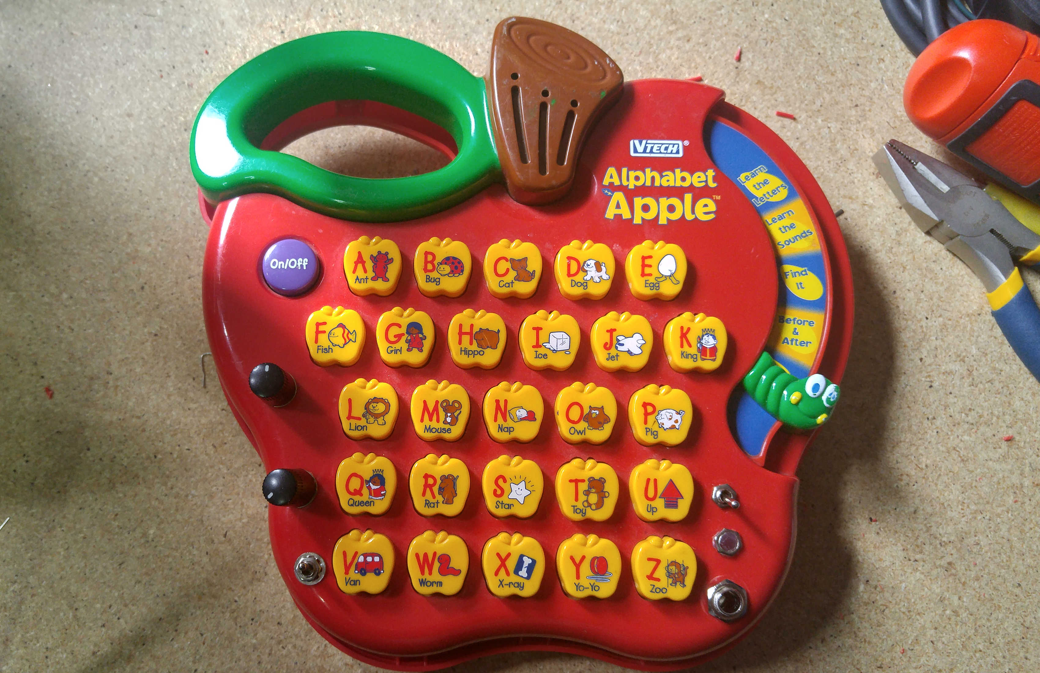
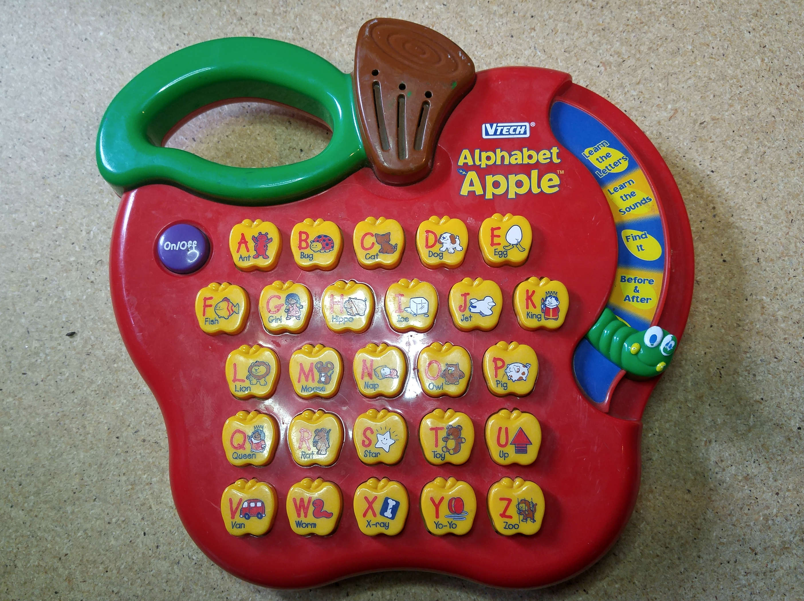
Though these modifications should work on nearly any toy you decide to modify the victim I will be demonstrating them on is a VTECH Alphabet Apple which I purchased from a local thrift store for 4$. When choosing a toy to bend I like to visit the local thrift stores (Value Village, Salvation Army, Goodwill) for two reasons, first you can get great toys for outrageously cheap and second it’s the easiest way to find toys from the 80s, 90s and early 2000s which are by far the best for bending.   There have been several iterations of the Alphabet Apple produced by Vtech with a similar aesthetics but very different internal workings, this particular model seems to be the most popular and was released early in the year 2000.

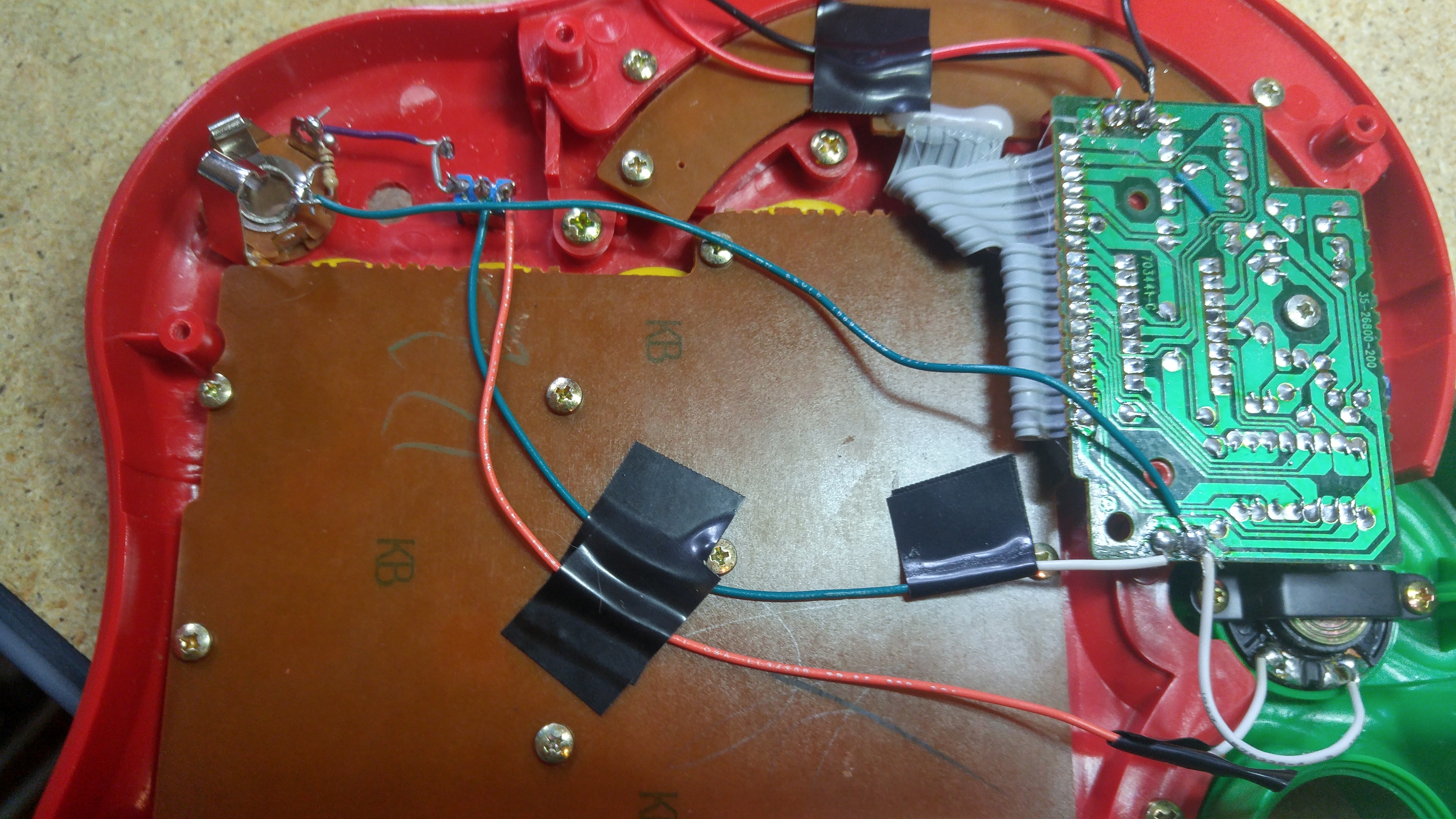
The first step once you get the screws out and open up the toy is to take pictures, lots and lots of pictures, using a digital camera or phone. These photos will allow you to mark down any bends or notes you find down the road and can also be used as a reference if anything goes wrong. Often times the cheap solder joints attaching the wires in these toys can come disconnected and the photos can help you reattach them where they belong. Here i s a picture of the circuit from my Apple :

Apple Circuit

The Kill Switch

When we circuit bend a toy we are forcing it to operate well outside of the factory parameters and this can cause …problems. We are forcing the processor to run at unusual speeds and sending data in and out of the chip sets in ways that were never planned for. Often this will cause the system to crash or lock up which can often only be rectified by removing the batteries and allowing the circuit to reset itself. This can be time consuming and frustrating, especially if the battery compartment is difficult to reach or needs to be unscrewed to access.

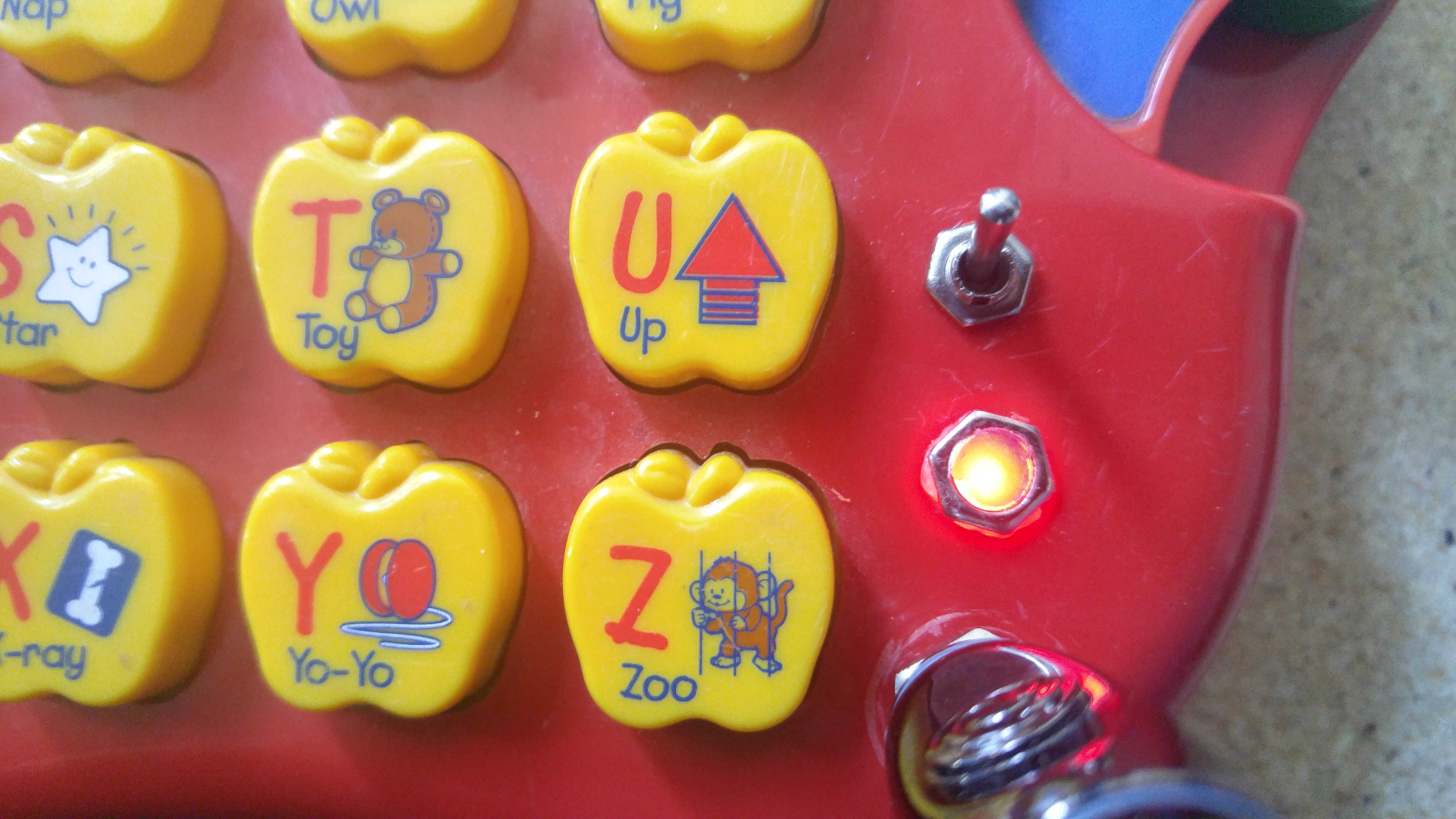
To simplify this we will add a basic switch along the red positive power line to allow us the disconnect the batteries at the flick of a switch. Simply cut and solder the switch onto the power line, drill a hole in the casing and mount it as seen below :

Kill Switch

Adding An Output

Next up we will be adding an audio out jack, this will allow you to send the audio signals from your toy to a mixer, an amplifier, headphones or even effects and filters. One thing which consistently amazes me is the quality of sound you can often get from these toys once you bypass the cheap built in speaker and run them through a proper playback device, not to mention how much deeper or more interesting you can make the output by running it through a couple simple filters, or perhaps a guitar pedal or two, the possibilities really are endless.

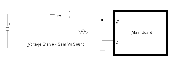
Before we get started lets have a look at a quick schematic to get an idea of what we will be doing :

Line Out

As you can see above this is a fairly simple procedure, essentially we will be cutting the positive wire going from the main circuit board to the speaker and adding a SPDT (on-on) switch. This switch will allow us to either send the signal from the board to the speaker normally allowing the toy to be played via the built in speaker or to divert the signal to an output jack we have added which will effectively turn off the built in speaker and send the signal through to whatever we plug the toy into. From here the sleeve tab on the jack is connected back to the point where the speaker wire returns to the board thus completing the circuit.

The resistor placed across the jack is there as a safety measure, most speakers have a certain level of impedance which the circuit was designed to have while running (You may have heard speakers referred to as 8 ohm or 4 ohm speakers this refers to the impedance or “resistance” they place in the circuit) Since we’ve bypassed the speaker we have removed this impedance from the circuit and need to replace it with the resistor.

Before we wire this it is important to inspect the toy and decide where the switch and jack will be placed, I generally like to drill my holes and insert the components before doing the majority of my soldering but this is really a matter of personal taste and depends how tight a space you are working with. Be especially careful when placing the 1/4 inch jack, make sure to leave enough room behind it not just for the connectors on the plug but for the male 1/4 inch jack which will be inserted into it.

Output wiring

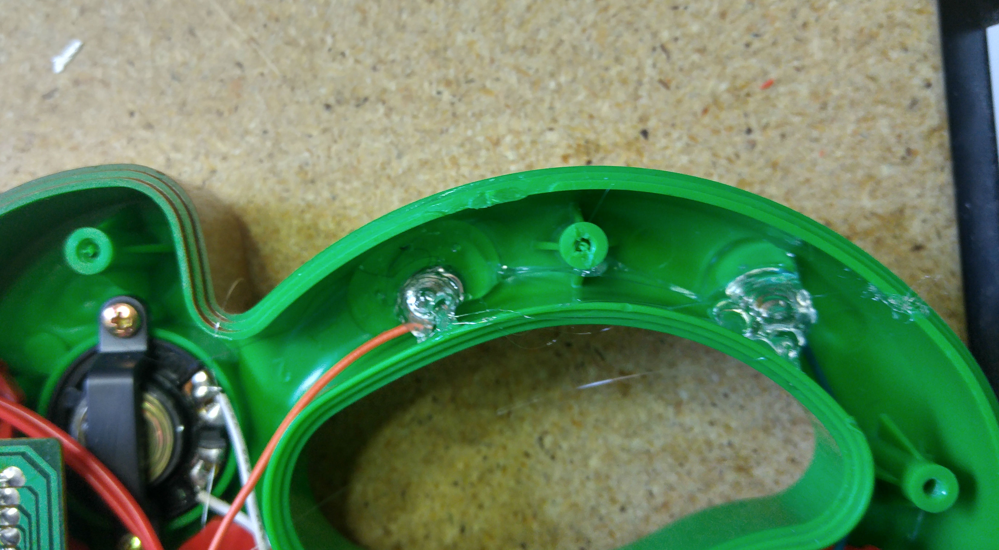
Once you’ve planned the location for the components you can wire them to the circuit. Take care to leave enough wire to reach from the board to the components without leaving an unnecessary amount of slack. The green and orange wires which are taped to the back of the keypad lead from the board (at the speaker output) down to the center pin of the switch and then from one of the outer pins of the switch back up to the positive side of the speaker. From the opposite outer pin of the switch you can see the small purple wire leading to the jack tab, the 10 ohm resistor across the jack and the second green wire leading from the ground (or sleeve) on the jack back to the audio return on the circuit board. Give it a test and you should be in business.

Now that we have these two simple modifications in place we are able to quickly cut power and reset the toy if we run into a crash or lock up, and we can pipe the audio from the toy directly into any other device which will accept an audio input. With only a handful of solder connections and four or five components we have transformed this simple toy into something much more versatile and have prepared it for the treachery we will soon be visiting upon it. Now the real fun can begin, Next time we will be looking at adding a pitch bend knob to the device and will begin searching for some glitches we can exploit to turn this “Learning Device” into an outlandish electronic instrument.

Click Here To Continue With Part 2


Sourcing Parts

There are a number of great sources where you can purchase components as needed, today I’d like to go through a few of the ones I’ve used and hopefully give you an idea of where you can go to get all the parts you’ll need for any project you tackle. This is by no means a comprehensive list but the below suppliers are where I source the majority of my parts.

Local

Buying local is typically the most expensive way to get parts but that is balanced out by the instant gratification you receive from walking into a store, giving them your money and walking out with your components. Though I wouldn’t recommend purchasing large quantities of parts in this way it is incredibly useful to have a store you can run to if you find yourself missing a specific piece you need to complete your project. Not to mention the right shop’s staff can be an excellent source of expert advice.

Radio Shack – I’ve read and been told that Radio Shack can be a good source of parts but unfortunately where I am located (In Ontario) we only have Circuit City which I have not had very much luck with. Typically their prices are extremely high and the selection is almost none existent.

Independent Stores – Independently owned electronics retailers are typically your best bet for a local parts supplier, if you can find one… Unfortunately due to competition with online retailers and the niche nature of their products these shops are getting harder and harder to find, but if you live in a large enough city have a look around and you may find something great. Typically you will pay substantially more than you would ordering parts online but you will be able to get the components you need without causing delays to your project.

Online

All Electronics – All Electronics was the first site I began ordering from and I’ve always had good experiences with them. They have reasonable costs and an easy to navigate site. Though they do not have as large a selection as some other suppliers this can actually be beneficial when your starting out, there is nothing worse than wading through a thousand different types of 10 ohm potentiometers just to try and find a volume control .

Jameco – Jameco is similar in scope to All Electronics though I’ve switched quite a bit of my business to them as I’ve found they stock a few more obscure parts (some CMos logic chips and the like) which I wasn’t able to find through All Electronics. My recommendation would be to try both these sites to get a feel for them and where both of there strengths lie.

Digikey – A moment ago when I mentioned wading through a thousand types of potentiometers… welcome to Digikey. I would recommend waiting until you are fairly comfortable with component types, manufacturers and specs. Often times without a specific part number for what you’re looking for you will end up sifting through page after page of near identical parts into oblivion. That being said if ever there is a part you can not find elsewhere or an IC too obscure to be widely available. Digikey will have it.

Building a Parts Library

Building a comprehensive component library is one of the most crucial steps to take as you delve deeper into the world of electronics. Having to order parts for each new project can be time consuming, cause delays as you wait for parts and limit your ability to experiment with different component values and test different circuit layouts to find what best suites your needs and tastes. That being said building a parts library is not something that happens over night, it is an ongoing process which will likely continue throughout your life in DIY. Today I’m going to go over a couple techniques I use to ensure my collection continues to grow. In an upcoming article I will also be going over a number of sites you can source parts from, which ones I prefer and what situations each is best for.

Click Here To Read More