Kirchoff’s Laws are two rules which serve to extend Ohm’s Law beyond simple linear circuits and allow you to begin analyzing more complex circuits involving multiple Nodes and Branches. These laws can be extended to work with time dependent components like capacitors and inductors as well as AC circuits however for today I will be focusing on DC resistor circuits. By doing so I hope to introduce these laws in the simplest possible use-case and leave expanding on them to a future article.
Kirchoff’s Current Law

The first of Kirchoff’s two laws states that the sum off all currents flowing into a Node is equal to zero. Put another way this means the current flowing into a Node is equal to the current flowing out. Looking at the Node shown above, if we know i1 is 3A, i2 is 7A and i3 is -5A (5 amps flowing out of the node) we can solve for i4. i1 + i2 + i3 + i4 = 0 becomes 3 + 7 – 5 + i4 = 0. by rearranging this we can say that i4 = -3 – 7 + 5 = -5.
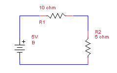
This rule can be used to reinforce an important intuition regarding linear circuits. If we look at any of the Nodes above (between B and R1, R1 and R2 or R2 and B) we see that each Node only has one branch leading into it and one leading out. Using the above equation that means i1 + i2 = 0 or i1 = -i2. Put simply this means that current is constant when circuit elements are placed in series. Since the circuit above is entirely made of elements connected in series the current throughout is constant and can be solved using Ohm’s Law. V = IR = I(R1 + R2) which can be rearranged to solve for current: I = V/(R1 + R2) making I = 5/15 = 1/3 A. You may notice that adding together series resistors is exactly the technique we used when looking at equivalent resistors. Kirchoff’s Current Law is the reason we were able to do so.
Kirchoff’s Voltage Law

Kirchoff’s second law states that the sum of the voltages around a closed loop is always equal to zero. This functions as an extension of Ohm’s Law as we have used it in series circuits. We start out with a similar equation to the one we used for the current rule except instead of using the current in a node we are working with the voltages around a loop (A loop being any path you can take around the circuit which ends at the same node you started at). Traveling around the loop we will see that V(B) + V(R1) + V(R2) = 0. The battery in this equation is 5 V but to solve for the voltage of the resistors we must use our friend Ohm. For each resistor V=IR, using the current 1/3 A we solved for above this gives us voltages of 10/3 V (for R1) and 5/3 V (for R2). One last thing to note is that unlike the battery which supplies voltage to the circuit the resistors “resist” the voltage, so in our equation we will make them negative. This gives us: V(B) + V(R1) + V(R2) = 0 = V(B) – IR1 – IR2 = 5 – 5/3 – 10/3. This reduces to 0 = 5 – 5.
A common use for this rule is to find the Voltage at a specific point in the loop. If we wanted to know the voltage between R1 and R2 we can rearrange the equation to get V(Node) = 5V – IR1 (Which for this simplified case would be equal to V(R2)).