
When I first started working with DIY electronics and synthesis I seemed to get the same advice everywhere I went. Every forum, blog and site I visited recommended one project to get started, The Atari Punk Console, and after building a few I can understand why. The Atari Punk Console (APC) is a simple yet rewarding project for beginners. With fairly limited parts it functions as a very basic standalone sound synthesizer but also has the capacity to be modified and controlled in a variety of interesting ways. This project is a great way to develop more experience soldering and circuit building and will serve as a platform as we begin to explore control voltage modules.
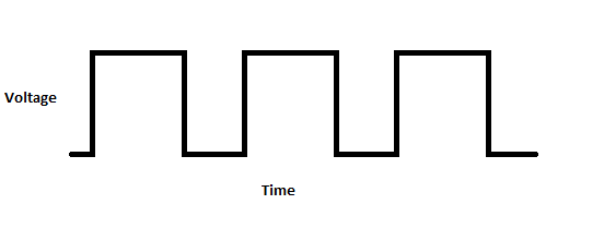
Before we get into this project I want to talk a little bit about wave forms. Wave forms are a way to track the movement of electricity within or output by a circuit. They can come in a variety of different shapes but today we will only be working with the most simple of them, The Square Wave. The best way to think of a square wave is like a switch being turned off and on. When you begin the switch is off and no power is flowing, after a moment you turn the switch on and the power instantly jumps to the voltage of the circuit and stays there until you turn the switch off again at which point it drops back down to zero. You can think of the diagram above as a switch being turned on and then off again at regular intervals. This is referred to as oscillation and typically happens extremely quickly within a circuit. In my explanation below when I talk about pulses I am referring to single sections of this square wave, the power going up, staying there for a moment and then dropping back down to zero.
How it works :
The Atari punk console uses 2 555 Timer circuits (conveniently packaged together in the 556 dual timer chip) to create noises. The first 555 circuit is set up in what is referred to as “Astable Mode”. This first circuit outputs short pulses at regular intervals. By adjusting the left knob on the APC we control the time between these pulses.
The second chip is set up in what is called “Monostable Mode”. What this means is that each time the circuit is triggered it outputs a pulse of a specific length. By adjusting the right knob on the APC we adjust the length of this second longer pulse. When we send the short pulses from the first 555 circuit into the trigger pin of the second 555 chip we are able to adjust both the time between pulses (through the first circuit) and the length of each pulse (through the second.)
When a pulse is being emitted by the second circuit it will ignore any further triggers until the pulse ends which causes some interesting behavior in the final device. As you increase the frequency of pulses using the first circuit and increase the length of each pulse through the second circuit you will eventually reach a point where a new trigger pulse is sent before the first long pulse (from the second circuit) is finished. Basically what this means for the sound is that as you adjust the knobs on your Atari the pitch will rise or fall at a steady rate for a period then suddenly jump up or down a substantial amount, this is when your long pulses have started (or stopped) overlapping your trigger pulses. For this reason when this circuit was first designed by Forest M. Mims III back in the 70s he referred to is as a stepped tone generator in reference to this stepping up and down of pitch created.
What you’ll Need :
- 1 – 9V Battery
- 1 – 556 IC (or 2 555s)
- 2 -SPST switches
- 2 – SPST switches
- 2 – 470K – 500K ohm Potentiometers
- 1 – ¼ inch jack
- 1 – DC jack (an audio jack will work if necessary)
- 3 – Banana Jacks (or preference)
- 1 – LED (color of your choice)
- 2 – 0.01 UF capacitors
- 1 – 10 UF electrolytic capacitor
- 1 – 1K resistor
- 1 – 470 ohm resistor (or whatever suits your LED)
Let’s start by having a look at the circuit:

Remember not to panic if you are new to circuit diagrams, as with the LM386 amplifier this is much simpler than it looks. A few things to take note of as you familiarize yourself with this diagram, First of all you’ll notice that in order to make the diagram simpler the pins on the 556 have been moved around. This is a fairly common practice as if we were to draw the diagram with the pins where they would normally appear on the chip the picture would quickly begin to resemble a spider web of wires crossing each other everywhere. Take special care as you breadboard and eventually solder this project that you are referring to the numbers to get your connections to the right pins. Also take note of the LED (beside the battery) and the electrolytic capacitor (pin 9) both of these component must be correctly oriented in order to operate.
If you’ve looked at or built other Atari Punk Consoles you may notice I’ve made a few changes to the basic circuit. The first being the addition of 2 banana jacks attached to pins 3 and 11. These will allow you to input control voltage from other devices, If you aren’t familiar with control voltage don’t worry! I’ll be explaining it in more detail in future projects but in simple terms these jacks will allow us to control the APC using external devices (like a keyboard).
In order for control voltage (CV) to work the external control device needs to also be connected to the ground of your circuit, for this reason I’ve added a power output jack and an additional banana jack attached to the ground.
The final modification is found on the output, I’ve added a momentary button and switch as an extra method of control. This will allow you to send short burst of noise without having to turn the console on and off.
Since I used a line out instead of a speaker on the final build I found the signal to be extremely hot, If you run into a similar problem this can be solved by adding a resistor in series between 10 uf cap and the momentary switch/button and a second resistor from this same point to the ground. As a general rule the resistor to ground should be a significantly higher value than the one to the output but experiment with different values in the breadboarding phase to find the one which provides the best results.
Now that we’ve got the theory out of the way, Let’s start building!
Step One : Breadboarding
 I always start by breadboarding new circuits as it gives me a chance to explore the schematic, make sure all of my components are working correctly and try any modifications I’m interested in making to the original circuit. Before making any of the modifications I mentioned in my circuit diagram I was able to test them on a breadboard to ensure they worked correctly.
I start by placing the main chip of the circuit (In this case the 556 dual timer) in the center of my board and attaching my negative and positive power to the rails. From here I’ll review the circuit diagram and began making connections. I tend to start with the simplest connections, for instance on the circuit diagram above pin 5 is connected directly to 8. I’ll start there, then connect pin 4, 10 and 14 to power. Once I have worked through the entire diagram I will go back and check each pin in order, pin 1 connects through the potentiometer to power, pin 2 connects through a 1K ohm resistor to pin 2 and so on to make sure all connections are correct and complete. Any components which do not fit on the board can easily be connected via alligator clips.
 Once your satisfied that all connections are made you can connect it to an amplifier and give it a try (use your handy new DIY LM386 power amplifier if you’d like). If there are any problems you can go back and compare the circuit diagram to your breadboard, double check each of your connections and the orientation of the electrolytic capacitor.
Once the circuit is working this is where you can try any kind of modifications you are interested in, I will discuss this more in an upcoming project but it was at this point I made a very basic voltage control device and tried inputting different voltages into pins 3 and 11 to ensure we would be able to use them.
Once everything is working the way you want it we are ready for step 2!
Step 2 : Perf Board
 It’s time to begin moving the components to a more permanent circuit. There are a number of different types of perf board available, I tend to prefer single-hole board because I find it allows me to make very compact circuits. The downside is any connections on the board need to be created with solder and wire. If you are newer or less confident soldering you may find it easier to work with something like stripboard on which the holes are connected together in strips using copper pads. Working with stripboard requires a bit more planning regarding component placement but will make making connections and soldering much more simplistic. You may find other specialized perf boards which you enjoy working with as well, as an example you can get boards on which the holes are connected to match the holes on your breadboard which makes transferring the project from breadboard to perf extremely easy.
My process for populating the perf board is very similar to working on the breadboard, I start by placing the IC (556) in the middle of my board and work my way out pin by pin. The one big difference is that I will try to place all onboard components and get them soldered into place before I begin attaching potentiometers, switches, jacks or anything else which will be connected to the board with wires.

Once you’re satisfied with the layout you can begin soldering down your components one by one. Here is the same perf board from the bottom. Note I have left any of the pins and leads which have connections to off board components un-soldered to make connecting them easier.
Step 3 : The Box

When I’m planning a project I tend to find myself spending unreasonable amounts of time wandering aimlessly through department and discount stores wondering how I’m going to house this new widget I’m putting together. “Project Boxes” can be purchased from most electronic and DIY suppliers and can be quite effective but I find they have less character than a found or salvaged container. This time lightning struck when I was looking for cheap hardware for another unrelated project.
The reason we are dealing with the box this early in the project is simply because things are going to be fairly tight. When I chose this box of screws to be my final enclosure I was not 100% sure that I’d be able to fit everything in, and if I did I knew space would be at a premium so I needed to plan my connections and layout carefully.

Once I had taken out the nuts and bolts and removed the hanger tab from the top of the enclosure I began laying each of the components on top of the box and moving them around until I decided on a final layout. Once I’d decided on their locations I started drilling holes for each component and screwing them loosely into place.

Here is the box once all of the components are loosely attached. I found my perf board was slightly too large when I was trying to fit it into the enclosure and had to cut off some of the unused space. I accomplished this by deeply scoring the board with a box cutter (be very careful doing so) and then breaking it along the score. I also trimmed down the internal separators inside the box so that wires could run over them (I did however leave most of the wall surrounding the battery to hold it in place.
Step 4 : Wiring Our Atari Punk Console


Now that the board and the box are ready to go it’s time to begin connecting everything together. I typically start with the battery connection and switch and then work my way through the other connections. Due to the space constraints with this project I opted to solder most of the components while they were in the box so I could make sure the wires would fit nicely once completed.

Once I had completed the wiring in the box I made the necessary connections to the board. I was able to cover the uninsulated leads on the LED and resistor connected to the power switch using electric tape to protect from them touching something else in the box and shorting. I also used electric tape to anchor some of the loose wires and generally clean things up inside the box. At this point as well it’s a good idea to test it to make sure everything is up and running. If it doesn’t start up or doesn’t make noise use your multimeter to recheck your solder connections, In my experience 9 out of 10 times the issues I’ve had with circuits and projects were caused by a weak solder connection somewhere within the device.
Step 5 : Make Some Noise!

Pop In a battery, close up your enclosure and you’re in business! Plug the Atari Punk Console into an amplifier and have some fun with it!