Basic Bends – Little Tikes Pop Tunes Keyboard

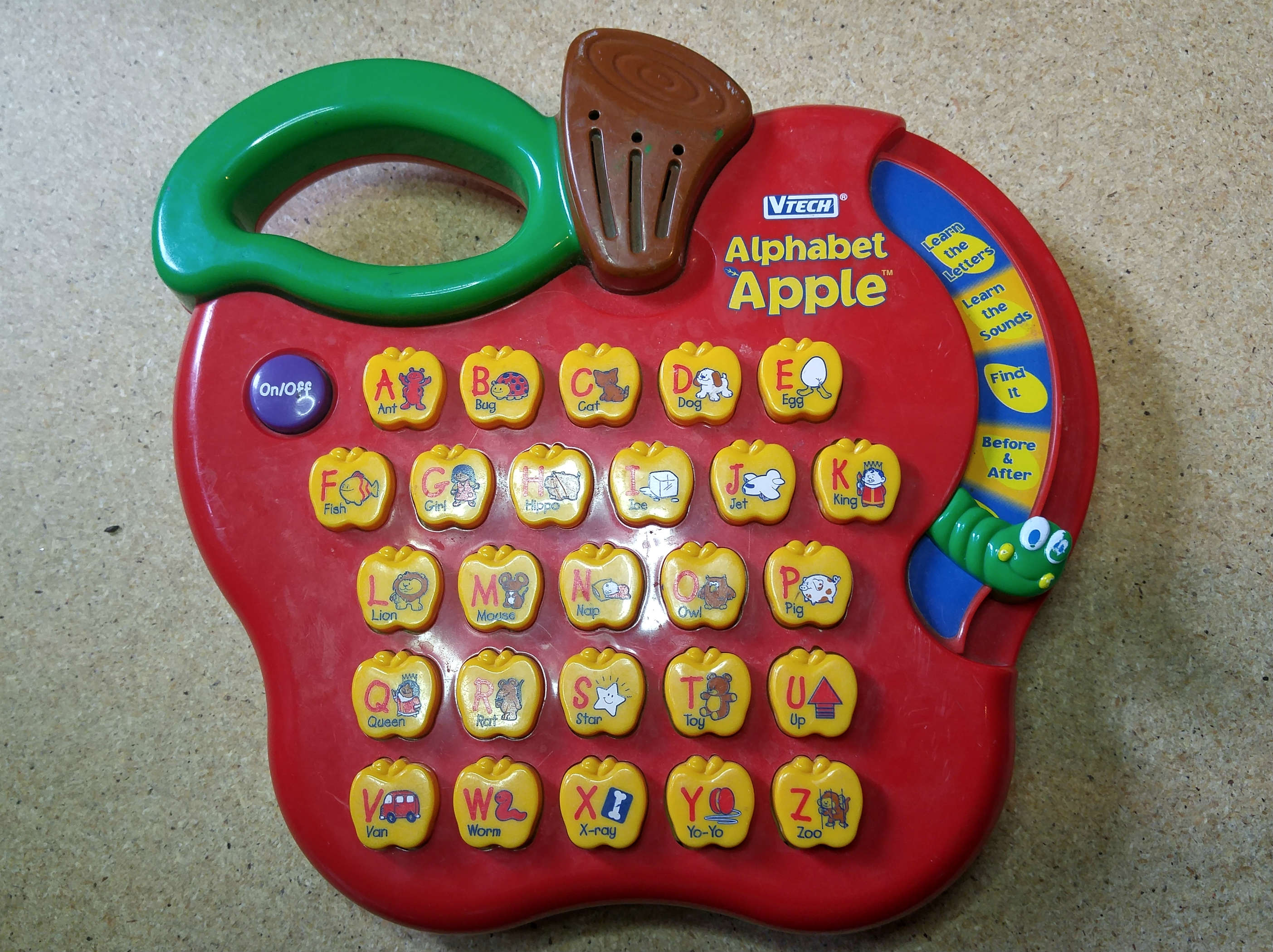
The latest toy to come across my work bench was a Little Tykes Pop Tunes Keyboard. This toy stood out to me at the thrift store for a few reasons. First and most obvious is the awesome LED ring located between the power knob and speakers. Further it had some weight to it and appeared to be solidly constructed which gave me some hope for what may be found inside. Finally the song samples made it stand out from a lot of other toy keyboards I had played with. Rather than ear shattering renditions of “Old MacDonald” or “Mary Had a Little Lamb” the pop tunes keyboard featured recognizable (if a bit outdated) popular music  (“ABC” by the Jackson 5 for example).

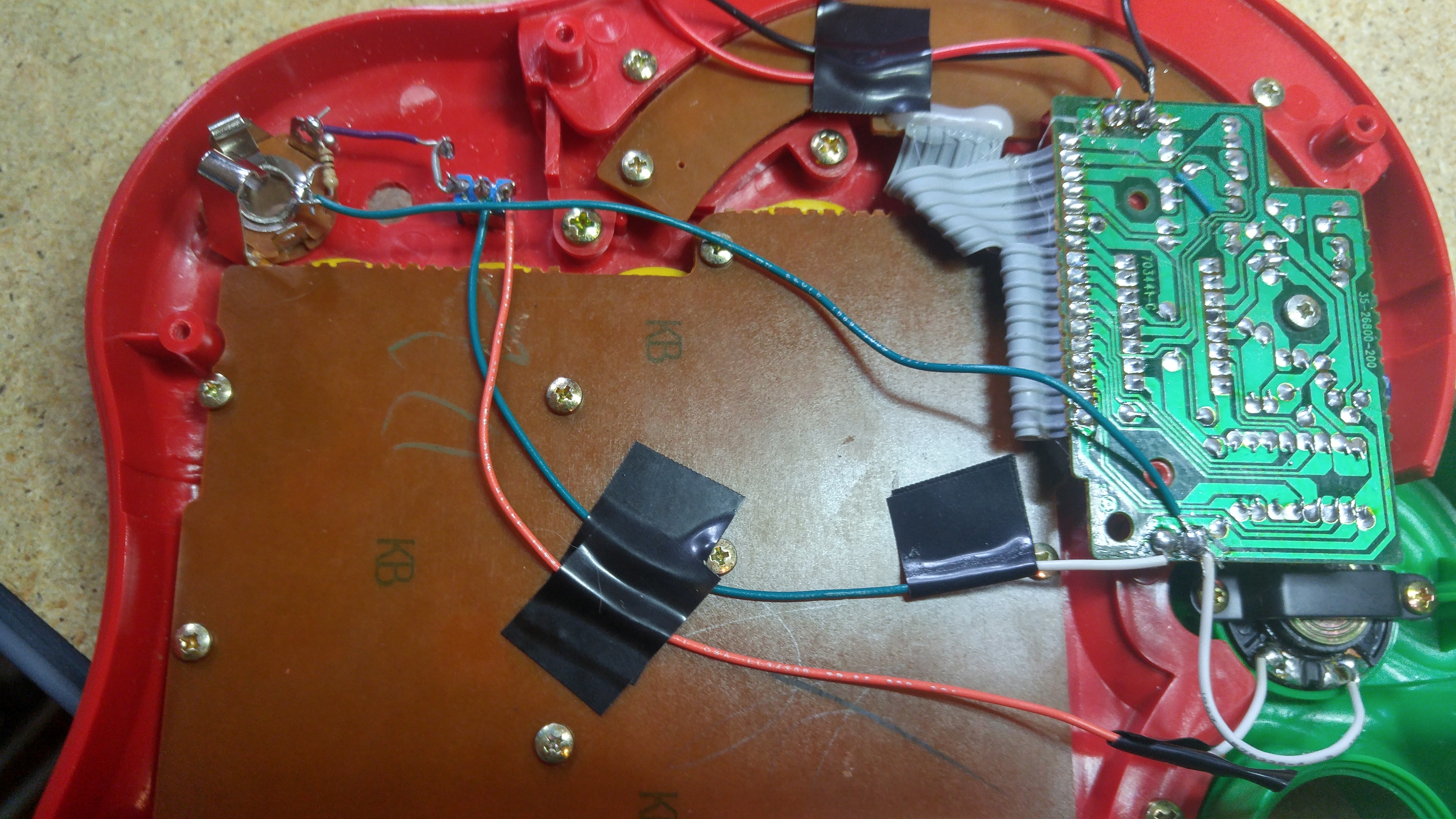
Upon opening it up I found a fairly simple SMD circuit board with a black blob IC. There were quite a few transistors and resistors though a large quantity of them seemed to be associated with the LED functionality. Still there was plenty to play with so I set to it.

The first step (as with all my toys) was to set up a kill switch and line out for the toy. For the kill switch I simply cut the battery positive wire and placed a switch on it. As far as the line out I cut the speaker positive wire and ran it through a toggle on – on switch. The other side of the on – on switch I ran through a 1K resistor and into the tip of a 1/4 inch jack. I then placed a 10K ohm resistor between the tip and ground and ran a wire from the ground back to the ground point on the speaker. I recommend experimenting with different resistor values to get the volume level you require as it can vary from device to device and also depending on where you are sending the signal.

Next up I set up a pitch bend on my Pop Tunes Keyboard. First off a big thank you to alienmeatsack who made a great post about this toy on Electro-Music.com and led me to this bend. This pitch bend is slightly different than the ones I’ve used in the past as it makes use of three points on the board rather than replacing a single resistor. For this bend I used R1 as the pitch base and soldered it to the center pin of a potentiometer. I then connected the outer pins of the potenetiometer to R07 and R011 which shift the pitch up and down respectively. The toy will crash if you shift to far to either side so you may want to buffer the pot with resistors on the outside pins. I found around 4K to 5K worked fairly well for this but there is no substitute for experimentation.

I was blown away by the low end bass when the pitch was shifted down on this device. The quality of the rumbling drones you can produce are just incredible for a toy like this.

Alienmeatsack also talked about getting good results from a voltage starve on this device so I may try that out. And I’ve found a few glitchy areas on the board which I would like to investigate. I should be back to update you on my progress soon.

NOTE : Shortly after writing this post I was experimenting on this board trying to force a loop when one of the resistors cooked itself… There was a little puff of smoke and many tears. I will come back to this toy and see if I can replace the resistor and get it running again but it may be on it’s way to toy heaven. This problem was not caused by the pitch bend which seems to be very stable and produced excellent results but if you are exploring the board be careful as some of the resistors appear to have a very low tolerance.

VTech Apple Part 1 – Kill Switch and Line Out

Lately I’ve been playing around with circuit bending and wanted to share some of my progress with you as I have found it to be an interesting and rewarding way to create new and unique instruments. I will be posting more complex bends and projects in future but before we get too deep into circuit bending I wanted to quickly go over two simple modifications which I do to essentially every toy I bend. Today I’m going to add a simple kill switch and a switched output to my VTech Alphabet Apple toy. These modifications are a great way to start getting familiar with the circuitry of a new toy and can prove invaluable as you continue exploring and bending the circuit and developing it into a unique and bizarre noise machine.

Our Victim

VTECH Alphabet Apple untouched

Though these modifications should work on nearly any toy you decide to modify the victim I will be demonstrating them on is a VTECH Alphabet Apple which I purchased from a local thrift store for 4$. When choosing a toy to bend I like to visit the local thrift stores (Value Village, Salvation Army, Goodwill) for two reasons, first you can get great toys for outrageously cheap and second it’s the easiest way to find toys from the 80s, 90s and early 2000s which are by far the best for bending.   There have been several iterations of the Alphabet Apple produced by Vtech with a similar aesthetics but very different internal workings, this particular model seems to be the most popular and was released early in the year 2000.

The first step once you get the screws out and open up the toy is to take pictures, lots and lots of pictures, using a digital camera or phone. These photos will allow you to mark down any bends or notes you find down the road and can also be used as a reference if anything goes wrong. Often times the cheap solder joints attaching the wires in these toys can come disconnected and the photos can help you reattach them where they belong. Here i s a picture of the circuit from my Apple :

Apple Circuit

The Kill Switch

When we circuit bend a toy we are forcing it to operate well outside of the factory parameters and this can cause …problems. We are forcing the processor to run at unusual speeds and sending data in and out of the chip sets in ways that were never planned for. Often this will cause the system to crash or lock up which can often only be rectified by removing the batteries and allowing the circuit to reset itself. This can be time consuming and frustrating, especially if the battery compartment is difficult to reach or needs to be unscrewed to access.

To simplify this we will add a basic switch along the red positive power line to allow us the disconnect the batteries at the flick of a switch. Simply cut and solder the switch onto the power line, drill a hole in the casing and mount it as seen below :

Kill Switch

Adding An Output

Next up we will be adding an audio out jack, this will allow you to send the audio signals from your toy to a mixer, an amplifier, headphones or even effects and filters. One thing which consistently amazes me is the quality of sound you can often get from these toys once you bypass the cheap built in speaker and run them through a proper playback device, not to mention how much deeper or more interesting you can make the output by running it through a couple simple filters, or perhaps a guitar pedal or two, the possibilities really are endless.

Before we get started lets have a look at a quick schematic to get an idea of what we will be doing :

Line Out

As you can see above this is a fairly simple procedure, essentially we will be cutting the positive wire going from the main circuit board to the speaker and adding a SPDT (on-on) switch. This switch will allow us to either send the signal from the board to the speaker normally allowing the toy to be played via the built in speaker or to divert the signal to an output jack we have added which will effectively turn off the built in speaker and send the signal through to whatever we plug the toy into. From here the sleeve tab on the jack is connected back to the point where the speaker wire returns to the board thus completing the circuit.

The resistor placed across the jack is there as a safety measure, most speakers have a certain level of impedance which the circuit was designed to have while running (You may have heard speakers referred to as 8 ohm or 4 ohm speakers this refers to the impedance or “resistance” they place in the circuit) Since we’ve bypassed the speaker we have removed this impedance from the circuit and need to replace it with the resistor.

Before we wire this it is important to inspect the toy and decide where the switch and jack will be placed, I generally like to drill my holes and insert the components before doing the majority of my soldering but this is really a matter of personal taste and depends how tight a space you are working with. Be especially careful when placing the 1/4 inch jack, make sure to leave enough room behind it not just for the connectors on the plug but for the male 1/4 inch jack which will be inserted into it.

Output wiring

Once you’ve planned the location for the components you can wire them to the circuit. Take care to leave enough wire to reach from the board to the components without leaving an unnecessary amount of slack. The green and orange wires which are taped to the back of the keypad lead from the board (at the speaker output) down to the center pin of the switch and then from one of the outer pins of the switch back up to the positive side of the speaker. From the opposite outer pin of the switch you can see the small purple wire leading to the jack tab, the 10 ohm resistor across the jack and the second green wire leading from the ground (or sleeve) on the jack back to the audio return on the circuit board. Give it a test and you should be in business.

Now that we have these two simple modifications in place we are able to quickly cut power and reset the toy if we run into a crash or lock up, and we can pipe the audio from the toy directly into any other device which will accept an audio input. With only a handful of solder connections and four or five components we have transformed this simple toy into something much more versatile and have prepared it for the treachery we will soon be visiting upon it. Now the real fun can begin, Next time we will be looking at adding a pitch bend knob to the device and will begin searching for some glitches we can exploit to turn this “Learning Device” into an outlandish electronic instrument.

Click Here To Continue With Part 2