Skip to main content
General
- Oscillator – Oscillators are the key to audio synthesis. They are circuits which output a current which varies at a regular speed between 2 set voltages. These oscillations are measured in hertz which is equal to cycles per second. For this to be audible it has to happen quite quickly as the audible range is typically between 20 – 20,000 hertz.
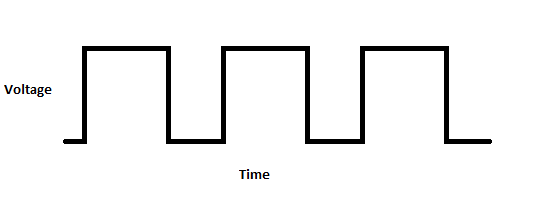
- Wave Form – Wave forms are how we describe oscillation within and output by a circuit. A wave form diagram is essentially a grid which displays the rise and fall of the voltage over time (see a simple square wave diagram below) the type of wave form is defined by the way the voltage rises and falls. As an example in the square wave shown below the voltage jumps up and down between the minimum and maximum voltage instantly, because the resulting grid looks square, we call it a square wave. Alternatively in a triangle wave the voltage rises at a steady pace until it reaches maximum voltage and then begins falling at the same rate until it reaches the minimum, This creates a triangle shape and is therefor called a triangle wave (see the pattern?). Other notable wave forms include the saw-tooth wave, the sine wave, ramp-up and ramp-down waves, and many others. Each type of waveform produces its own unique sound when output through a speaker.
- Control Voltage – Control voltage is a common method of controlling your various synth components. A control voltage can be generated in a variety of ways (including keyboards, sequencers, low frequency oscillators and so on). In practice it is a low voltage (usually o-5V) which you input into a circuit to modify it’s operation. Take as an example a basic CV keyboard, As you move up the keyboard each key will output a slightly different voltage, when these voltages are then input into a voltage controlled oscillator the oscillator runs at progressively faster rates which produce progressively higher notes.
Module Types
- Voltage Controlled Oscillator (VCO) – As the name implies a VCO is an oscillator which can be controlled by voltage. VCOs are the primary audio source in most synthesizers. By oscillating they produce an audible tone which can be manipulated by inputting voltage into their circuit.
- Low Frequency Oscillator (LFO) – A low frequency oscillator is a type of oscillator which oscillates below the audible range, The output from LFOs can be used as a control voltage and inputted into other components like a VCO or VCA
- Voltage Controlled Amplifier (VCA) – An amplifier that can be adjusted remotely by inputting voltage into the circuit. Depending on the type of control voltage you are inputting this can either turn the amplifier on or off when for instance a key on a keyboard is pressed, or sweep the volume gradually up and down.
- Envelope Generator – An envelope generator is usually used to control a VCA. Typically a keyboard or other control voltage device will output a trigger pulse each time a note is meant to begin (for instance when a key is pressed). Instead of just turning the amplifier on instantly the envelope generator will take that trigger pulse and tell the amplifier how quickly to turn on, how long to stay on and how quickly to turn off allowing you to have the notes ramp up or sustain when they are played.
- Sequencers – A sequencer is another method of creating control voltages to input into VCOs or VCAs. A sequencer will have a number of “steps” each of which can be controlled by a potentiometer. The potentiometer allows you to modify the voltage output by each step which will in turn modify the tone created by your VCO. They sequencer will then cycle through the steps allowing you to create a repeating melody.
- Filters – Available in both low pass and high pass varieties these will remove any signal lower or higher than a set cutoff level
Circuit Bending
- Circuit Bending – The art of exploring and modifying audio circuits to produce new sound capabilities
- A Bend – A connection between two parts on an audio circuit which changes the behavior of the circuit, Bends are typically include a switch, a potentiometer, a photoresistor, body contacts or other method of control
- Body Contacts – Exposed metal on the outside of your device connected to specific solder points on the circuit board of the device, by placing your hand on these points you can connect them and add resistance (placing your body into the circuit)
- Lick and Stick – A common bending practice through which you lick a finger and press it lightly onto the circuit board, helpful for identifying bend points (Goes by many names)