I just wanted to make a quick post to let you guys know about an update to The Basics section of this site. I’ve added an overview of Nodes and Branches as an introduction to these two terms in preparation for future additions looking into Kirchoffs Rules, Nodal and Mesh Analysis and Thevinin Analysis.
The Basics
Intro to Bipolar Power Supplies

As you begin to tackle more complex and interesting synthesizer components you may begin to encounter schematics for circuits which require both a positive and a negative power input to operate. As an example Eurorack synth modules use plus and minus 12V power supplies. As a result many DIY synth enthusiasts will also use +\- 12V so that they can interface with their Eurorack Modular set-ups. This is referred to as a bipolar power supply and is necessary for circuits which include operational amplifiers.
Unfortunately this can cause something of a tripping point for electronics or synthesizer beginners. When I first came across this it took me far longer than I like to admit to wrap my head around it. How could a voltage be negative? Do I need special equipment to power these circuits? This confusion was primarily caused by two misconceptions I held at the time:
Voltage is a measurement of force not quantity:
When we think about voltage we tend to think of it as a quantity. We assume that the voltage of a battery is the number of volts which that battery contains. This is perpetuated by the way we refer to voltage ; “This battery is 9V.” This is however not correct. The voltage we refer to with batteries, power supplies and circuits is actually the voltage difference between the positive and negative poles. If you are familiar with the water analogy for describing electricity you may have heard that voltage is the pressure which pushes the electricity through the circuit. If you had a pipe where you applied equal pressure to both ends the water would not move through it. If however you had a pipe where you applied a greater pressure to the water at one end of the pipe, the water would begin moving. Further the force with which the water moves through the pipe would be equivalent to the difference in pressure between the two ends of the pipe. Similarly with a 9V battery the voltage at the positive pole is 9V higher than the voltage at the negative pole which pushes the electricity from the positive pole, through your circuit, to the negative pole.
Consider then if you turned the circuit upside-down. This would mean the same 9V of force was still moving through the circuit. However now it is moving through the circuit in the opposite direction. The 9V of force would now be pulling electricity from the ground connection and pushing it to the power bus. This is what would be referred to as a negative voltage.
Ground is a reference point:
When I started working with electronics I did not have a firm grasp on what exactly ground was. I got used to using the negative pole of a battery as ground and began assuming that it was the lowest pole of the battery or power supply. This understanding served me fine with basic circuits but became a problem as I began working with op-amps and more complex circuitry. The truth of the matter is though that the ground is not an intrinsic point on the power supply and has more to do with the circuit itself than your power supply (That being said some power supplies include circuitry to anchor or shield their ground to make it more stable). The ground ultimately serves as a reference point from which the voltage of the circuit is measured. With some basic components you could set up a ground anywhere between the maximum voltage of your power source and 0V.

Consider the circuit above. The most intuitive way to approach this would be to say that ground is point C. In this case we would measure the voltage difference between B and C to determine that the voltage at point B is 9V. Similarly by measuring the voltage difference between A and C you can determine that the voltage at point A is 18V.
However if you approach the circuit differently you will see very different results. Lets say that we assign point B as ground in the circuit. In this case by measuring the voltage A and B to find that the voltage at point A is 9V. Next we would measure the voltage between C and B and find that the voltage at point C is negative 9V. This means the voltage at point C is 9V less than the voltage at ground (point B). The schematic shown above is the most basic bipolar power supply you can create and is perfect for developing familiarity with these types of circuits.
To make my life easier I soldered this small bipolar power supply together on a scrap of perf board I had on hand. I’ve added two large capacitors (330 uf electrolytic) to provide some decoupling for simple circuits. Additionally I placed leads on the positive, ground and negative traces so I could easily connect this supply to my breadboard.
If you are looking to free yourself from batteries I would strongly suggest looking into MFOs Wall Wart Bipolar Power Supply as an option for moving to a more permanent voltage source (along with the wonderful documentation provided with all of MFOs projects). Alternately if you have a traditional bench power supply there are many projects available to help you create a bipolar supply using the monopolar output these provide.
5 Tools To Stay Organized
I’m working away on some exiting new projects but until I get them finished I wanted to share some quick ways that I use to keep my workstation organized. With thousands of small parts, endless types and colors of cable and a pile of specialized tools it can be very easy to watch your workstation descend into chaos. Today I’ll go over a few quick tips to help you keep things organized so you can spend less time searching for tools and parts and more time focusing on your builds.
1 – Component Shelves
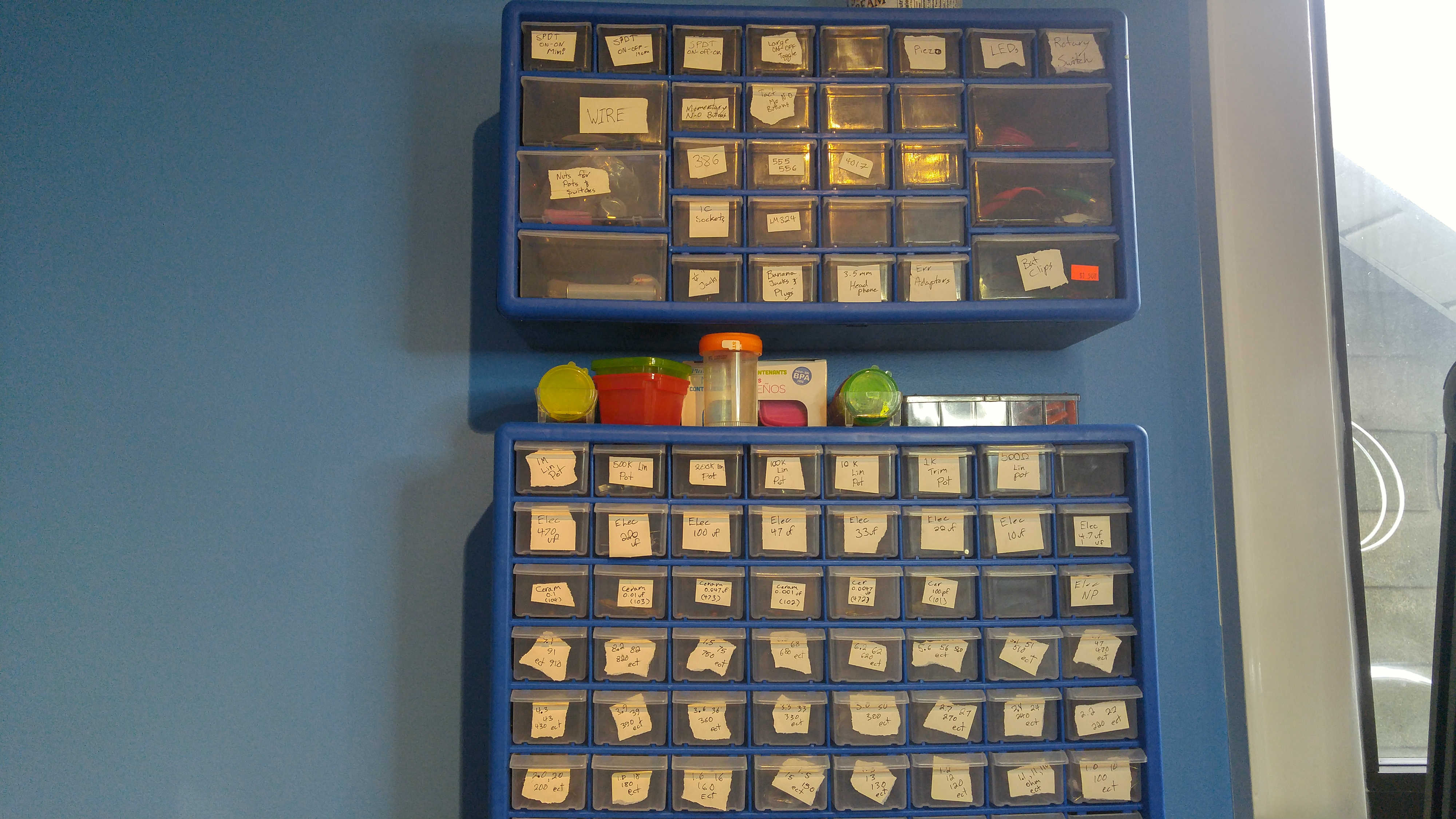
Component shelves can be purchased online from amazon or at most major hardware stores and I honestly can’t imagine my work area without them. I’d recommend purchasing a few of these as soon as you start exploring electronics, set up a sorting system and keep to it. This way instead of digging through a pile consisting of every resistor you own you can just reach out and grab it from the corresponding drawer.
2 – Wire Rack
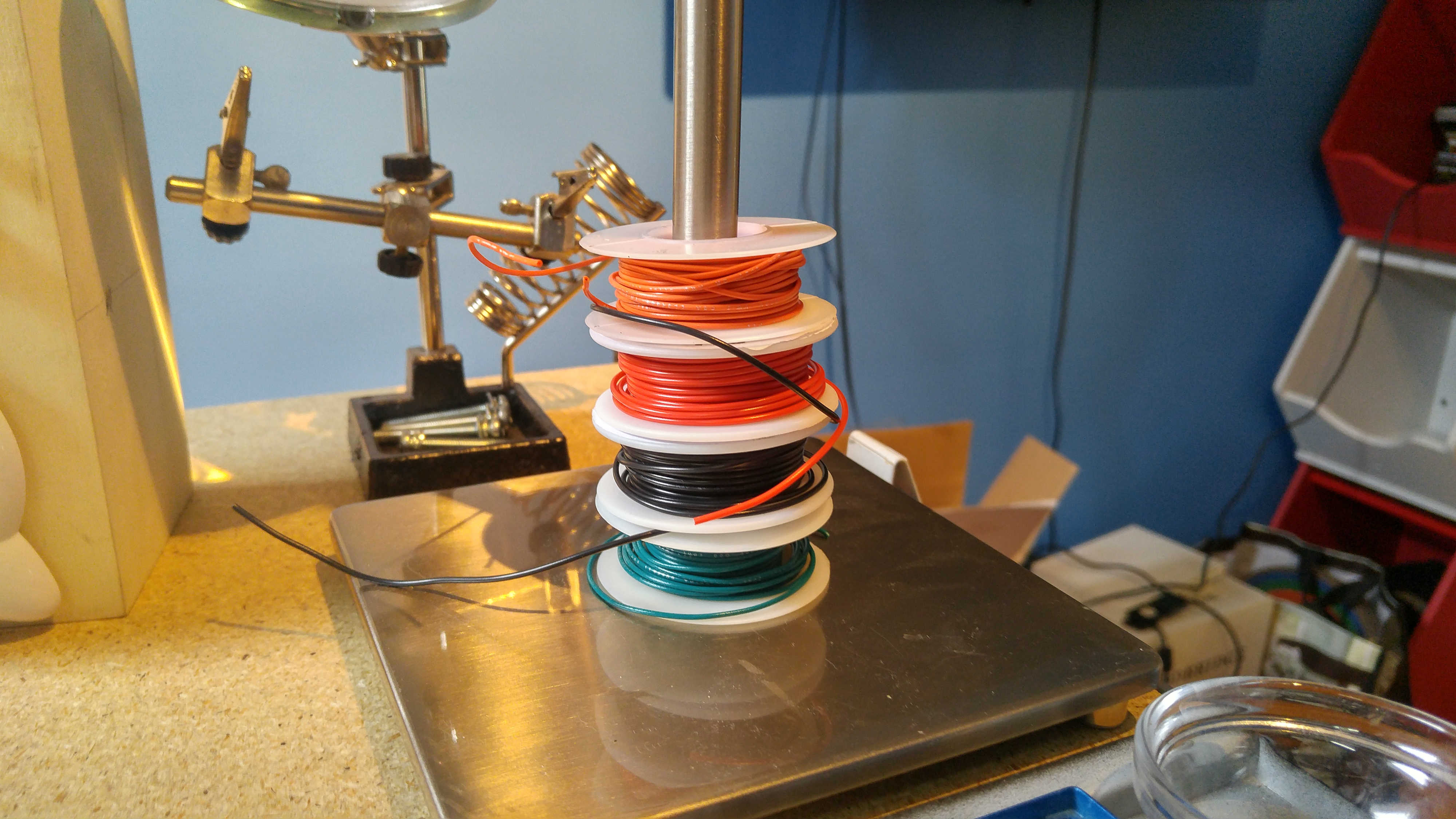
It doesn’t take long for your spools of wire to start unwinding and trailing around your workstation, the simple solution to this is to set up some kind of wire rack and place the spools onto it, this way you roll and unroll them with ease. There are commercially available wire racks though the one I use is actually an old broken lamp. Paper towel racks are also often very effective.
3 – Bins
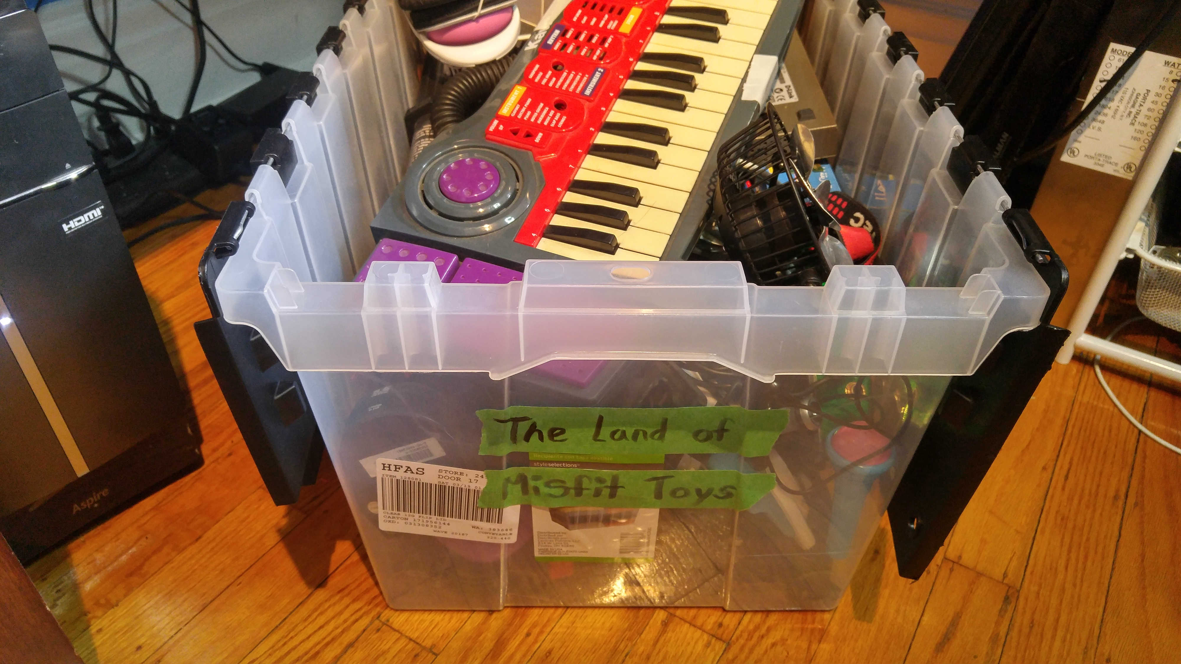
For parts or devices too large for your component drawer I keep a number of bins of various sizes on selves around my workstation, Label each bin and sort items into them as necessary. I have large bins for things like cables, toys and “Devices for Salvage” then there are smaller bins for things like adapters, alligator clips and speakers.
4 – Tool Baskets
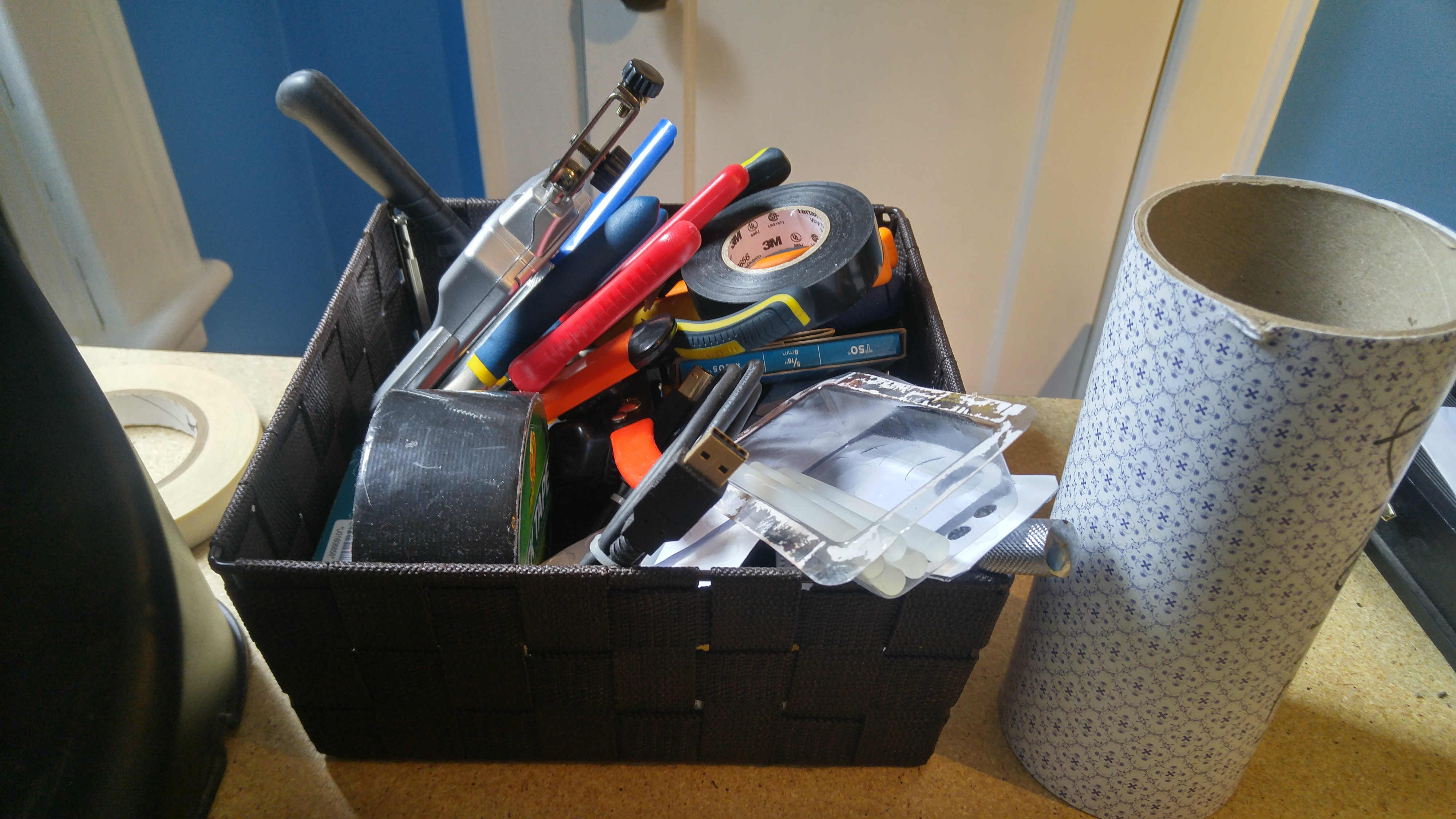
I keep a few baskets around my workstation which are where I store all of the common tools I use on a day to day basis so that they are at hand whenever I need them. In these baskets you can find things like pliers, wire strippers, angle cutters, a few screwdrivers and my solder remover.
5 – Small Containers
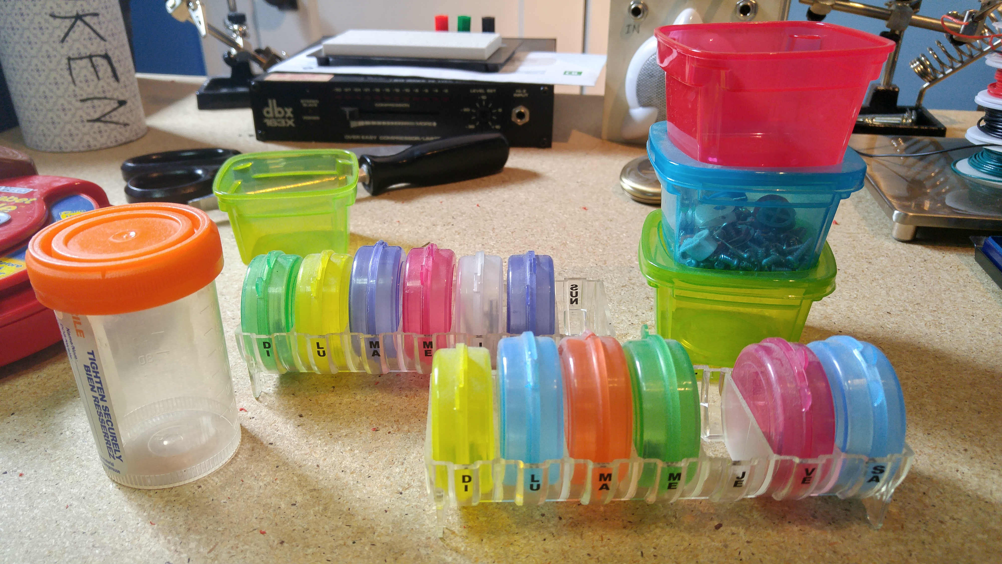
Small containers are great for holding all the hundreds of tiny screws you remove from devices as you take them apart, along with any other small parts that you remove and don’t want to lose. Typically I get these from dollar stores though daily dosage containers from pharmacies are excellent as well.
Awesome LEDs
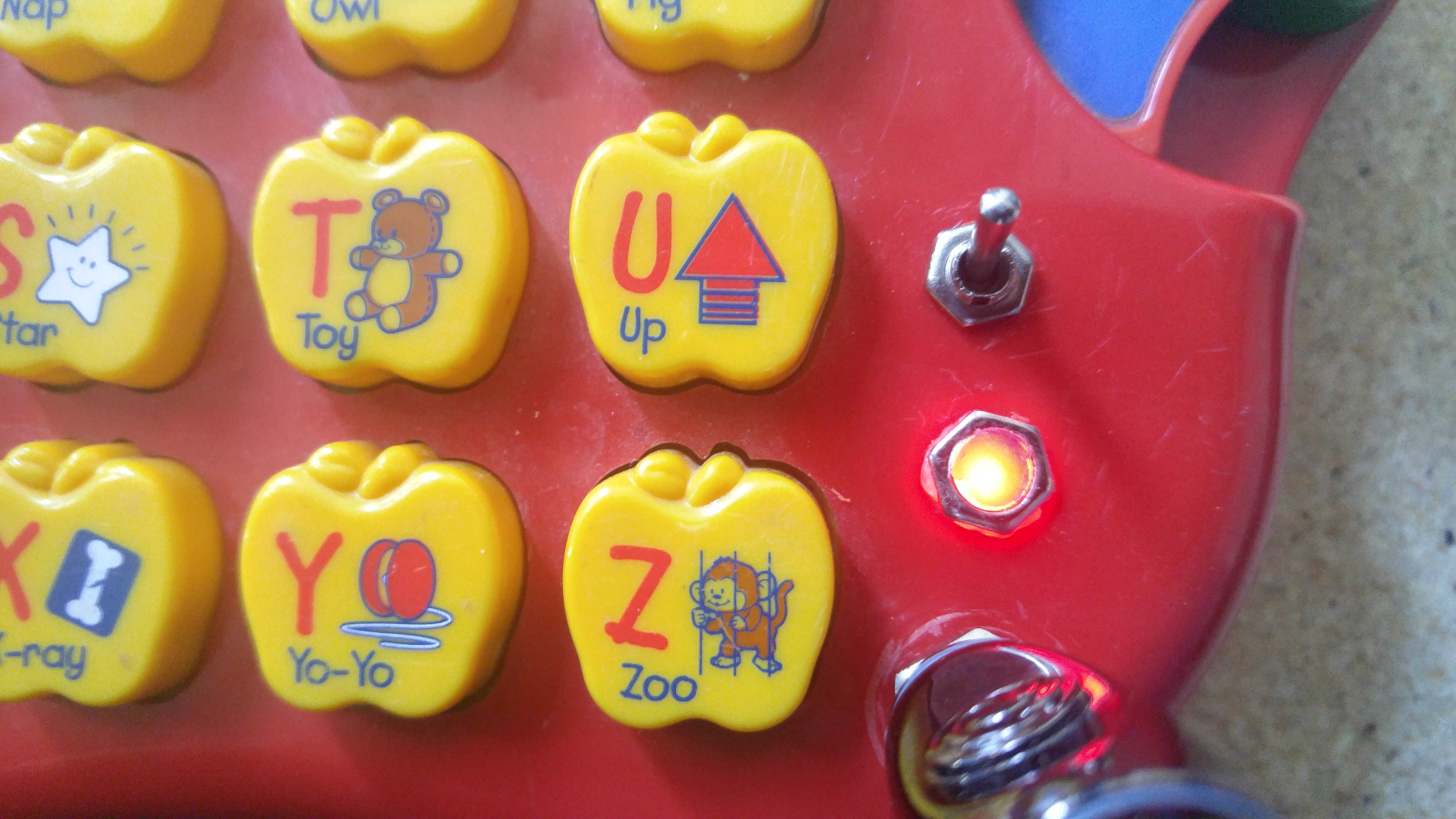
Whether its a circuit bent monstrosity or a simple oscillator, nothing brings a project to life quite like a couple LEDs. Today I wanted to show you an easy trick I picked up from a friend to give the LEDs you add to your projects a clean and professional look without having to spring for fancy lights or sleeves. All you need is some hot glue, a shallow nut or washer and some electric tape.
Start out by drilling a hole where you want the LED to be, This hole should be bigger than the LED itself and around the same size or slightly larger than the hole in your nut or washer. Once the hole is drilled line the washer or nut up with it and place a piece of electric tape over it. Take a moment to ensure the electric tape is taught and smooth over the hole in the nut and that it did not move when you were taping it down (It should still be lined up with the hole in your project).
Next we want to turn over or open up the device and pour a generous amount of hot glue into the hole from the back, allow it to heap up a bit on the inside of your device, before the glue has a chance to solidify push the LED into the hot glue, do your best to stop it just shy of pressing into the tape on the other side so there is still some glue between it and the tape. Once it is in place allow the glue to dry for a few moments, If you would like you can take this opportunity to wire the LED to the circuit (If you haven’t already)
Once the glue has completely dried gently remove the tape, You may need to use an Exacto knife to remove any excess glue leaving a smooth surface filling the hole in the nut. Since the glue is translucent when the light is turned on the entire hot glue plug will glow giving the appearance of a large flat bulb.
Sourcing Parts
There are a number of great sources where you can purchase components as needed, today I’d like to go through a few of the ones I’ve used and hopefully give you an idea of where you can go to get all the parts you’ll need for any project you tackle. This is by no means a comprehensive list but the below suppliers are where I source the majority of my parts.
Local
Buying local is typically the most expensive way to get parts but that is balanced out by the instant gratification you receive from walking into a store, giving them your money and walking out with your components. Though I wouldn’t recommend purchasing large quantities of parts in this way it is incredibly useful to have a store you can run to if you find yourself missing a specific piece you need to complete your project. Not to mention the right shop’s staff can be an excellent source of expert advice.
Radio Shack – I’ve read and been told that Radio Shack can be a good source of parts but unfortunately where I am located (In Ontario) we only have Circuit City which I have not had very much luck with. Typically their prices are extremely high and the selection is almost none existent.
Independent Stores – Independently owned electronics retailers are typically your best bet for a local parts supplier, if you can find one… Unfortunately due to competition with online retailers and the niche nature of their products these shops are getting harder and harder to find, but if you live in a large enough city have a look around and you may find something great. Typically you will pay substantially more than you would ordering parts online but you will be able to get the components you need without causing delays to your project.
Online
All Electronics – All Electronics was the first site I began ordering from and I’ve always had good experiences with them. They have reasonable costs and an easy to navigate site. Though they do not have as large a selection as some other suppliers this can actually be beneficial when your starting out, there is nothing worse than wading through a thousand different types of 10 ohm potentiometers just to try and find a volume control .
Jameco – Jameco is similar in scope to All Electronics though I’ve switched quite a bit of my business to them as I’ve found they stock a few more obscure parts (some CMos logic chips and the like) which I wasn’t able to find through All Electronics. My recommendation would be to try both these sites to get a feel for them and where both of there strengths lie.
Digikey – A moment ago when I mentioned wading through a thousand types of potentiometers… welcome to Digikey. I would recommend waiting until you are fairly comfortable with component types, manufacturers and specs. Often times without a specific part number for what you’re looking for you will end up sifting through page after page of near identical parts into oblivion. That being said if ever there is a part you can not find elsewhere or an IC too obscure to be widely available. Digikey will have it.
Building a Parts Library
Building a comprehensive component library is one of the most crucial steps to take as you delve deeper into the world of electronics. Having to order parts for each new project can be time consuming, cause delays as you wait for parts and limit your ability to experiment with different component values and test different circuit layouts to find what best suites your needs and tastes. That being said building a parts library is not something that happens over night, it is an ongoing process which will likely continue throughout your life in DIY. Today I’m going to go over a couple techniques I use to ensure my collection continues to grow. In an upcoming article I will also be going over a number of sites you can source parts from, which ones I prefer and what situations each is best for.
A Simple Explanation Of Ohm’s Law
 If you’ve spent time reading about electronics or DIY you’ve likely run into Ohms Law as it is one of the most fundamental building blocks to understanding how electronics work and designing circuits. The above diagram may even be familiar to you. But what does it all mean? Today I’d like to spend some time exploring Ohms Law to provide you with a greater understanding of the principal and of electronics as a whole.
Ohms Law describes the relationship between three basic elements of a circuit, The Voltage (V), Current (I) and Resistance (R) and shows how each of these values are interconnected.
The most common analogy used to describe this principle is to visualize a series of pipes with water flowing through them. Each of these values can be associated with a characteristic of the pipe system.
- Voltage – The force with which water is being pumped into your system, with electronics we can modify this by using higher voltage (or more) batteries or a higher voltage power supply.
- Resistance – The factors which restrict water flow through the pipe, for instance the width of the pipe or a partial cutoff valve. Resistance in a circuit can be added using resistors of various types
- Current – The speed at which water which flows through the pipe
Imagine if you had two sets of pipes which are identical width and length. But you attached them to different pumps, one of which had double the force of the first. The resistance against the water would be identical (Pipe Size) but because the voltage (pump strength) is higher on the second set of pipes the water will move much faster through it causing it to have a greater current. In order to make the current the same between the two we would either have to adjust the voltage (Pump Strength) of one of the pipes to make them equivalent or adjust the resistance (Pipe width) to make up for the difference.
Adjusting the resistance would balance out the difference in voltage allowing the same amount of water to flow.
Lets try a real world example. Lets say I have a light bulb which runs off 1 ampere (Current) and I have 2 AA batteries in series giving me 3V of power. How do I decide what value of resistor to use to complete the circuit?
Using Ohms law we know that R=V/I, which we can substitute the values from the above example to complete :
R = 3/1
R = 3 ohm
From here you can take a 3 ohm resistor off your shelf, plug it into the circuit and you are in business!
What Is Control Voltage?
Control Voltage (Often abbreviated to CV) is at it’s most basic a signal which can be applied to an analog circuit to modify it’s behavior. This modification can take many forms but typically with analog synthesis we will be using it to either turn a circuit on and off, or adjust the frequency and intensity of oscillation (which will adjust tone and volume). What makes this interesting is it allows us to modify or control various components of a synthesizer from a separate circuit or device. Probably the easiest example of this would be a basic CV keyboard, When you press a key on the keyboard a DC signal is sent from the keyboard to your synthesizer which tells the synthesizer what note to play and how long to play it. When you press different keys on the keyboard the signal sent will be a slightly different voltage which will modify the synthesizers oscillation, amplifier and envelope to different degrees thus producing different notes and sounds.
To continue reading please visit Control Voltage 101 in The Basics
Tools of the Trade

One of the best things about getting into electronics as a hobby is how accessible it is. You don’t need a shop or garage to work in, I do most of my soldering at a desk in my frankly tiny apartment. And perhaps even more importantly you don’t need to spend huge sums of money on tools to get past the starting gate, a usable toolkit can be put together for around 50 or 60 dollars and most of the parts you need can be found for small change. In the interest of helping you begin building your toolkit I’ve added a new article to the “Basics” area of this page. Have a look at The Tools of the Trade to get an idea of what tools you’ll need to get started in the exciting world of electronics DIY.
Definitions!
What is an oscillator? What is an control voltage? What is love? (Baby Don’t Hurt Me)
The first hurtle to overcome when getting into almost any new hobby is learning the language. The use of jargon can make new interests or hobbies seem unapproachable and confusing and can turn off many would be enthusiasts. I do my best to write my tutorials and projects using the simplest terms possible but as I move into more complex topics and projects the use of this jargon will become unavoidable. It is for this reason that I’ve added the first two pages to the basics area of this page. These are Electronics Definitions and Synthesis Definitions. Over time I will be adding definitions for all of the special terms I use for electronic components, measurements, synthesizer modules, and anything else that someone new to electronics DIY may not be familiar with.