Awesome LEDs

Vtech LEDs

Whether its a circuit bent monstrosity or a simple oscillator, nothing brings a project to life quite like a couple LEDs. Today I wanted to show you an easy trick I picked up from a friend to give the LEDs you add to your projects a clean and professional look without having to spring for fancy lights or sleeves. All you need is some hot glue, a shallow nut or washer and some electric tape.

Start out by drilling a hole where you want the LED to be, This hole should be bigger than the LED itself and around the same size or slightly larger than the hole in your nut or washer. Once the hole is drilled line the washer or nut up with it and place a piece of electric tape over it. Take a moment to ensure the electric tape is taught and smooth over the hole in the nut and that it did not move when you were taping it down (It should still be lined up with the hole in your project).

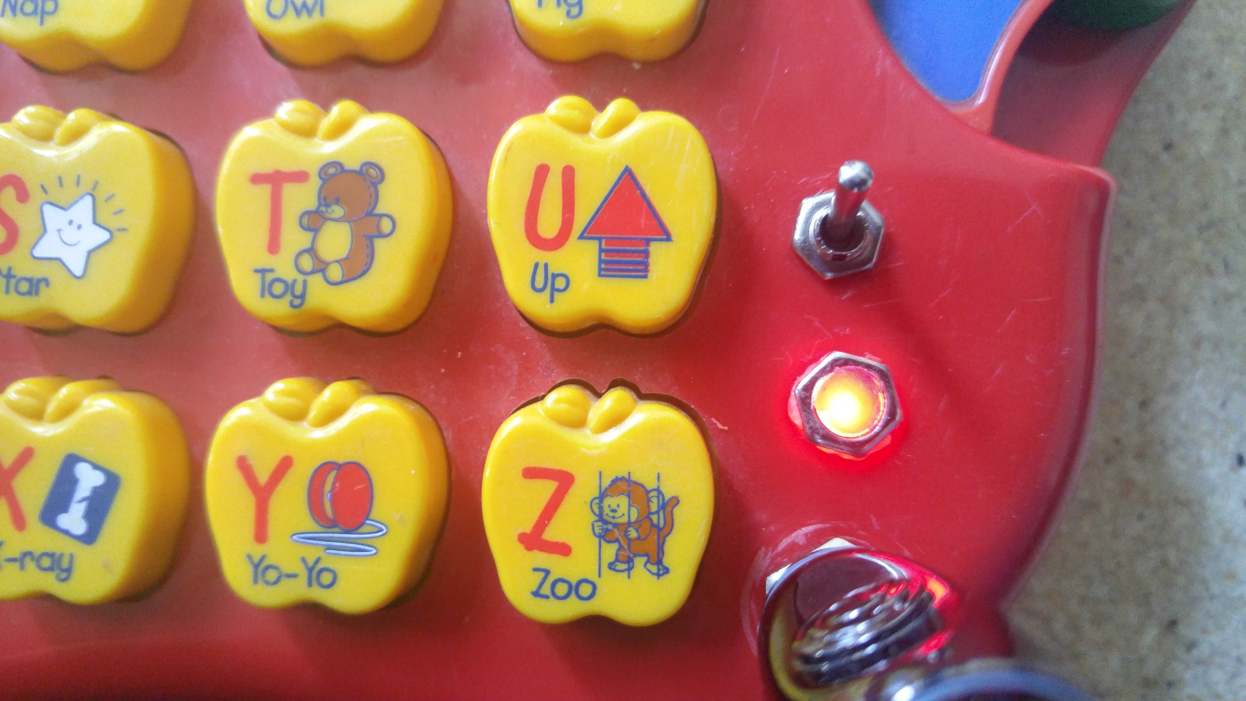
Next we want to turn over or open up the device and pour a generous amount of hot glue into the hole from the back, allow it to heap up a bit on the inside of your device, before the glue has a chance to solidify push the LED into the hot glue, do your best to stop it just shy of pressing into the tape on the other side so there is still some glue between it and the tape. Once it is in place allow the glue to dry for a few moments, If you would like you can take this opportunity to wire the LED to the circuit (If you haven’t already)

Once the glue has completely dried gently remove the tape, You may need to use an Exacto knife to remove any excess glue leaving a smooth surface filling the hole in the nut. Since the glue is translucent when the light is turned on the entire hot glue plug will glow giving the appearance of a large flat bulb.


A Simple Explanation Of Ohm’s Law

Ohms LawIf you’ve spent time reading about electronics or DIY you’ve likely run into Ohms Law as it is one of the most fundamental building blocks to understanding how electronics work and designing circuits. The above diagram may even be familiar to you. But what does it all mean? Today I’d like to spend some time exploring Ohms Law to provide you with a greater understanding of the principal and of electronics as a whole.

Ohms Law describes the relationship between three basic elements of a circuit, The Voltage (V), Current (I) and Resistance (R) and shows how each of these values are interconnected.

The most common analogy used to describe this principle is to visualize a series of pipes with water flowing through them. Each of these values can be associated with a characteristic of the pipe system.

  • Voltage – The force with which water is being pumped into your system, with electronics we can modify this by using higher voltage (or more) batteries or a higher voltage power supply.
  • Resistance – The factors which restrict water flow through the pipe, for instance the width of the pipe or a partial cutoff valve. Resistance in a circuit can be added using resistors of various types
  • Current – The speed at which water which flows through the pipe

Imagine if you had two sets of pipes which are identical width and length. But you attached them to different pumps, one of which had double the force of the first. The resistance against the water would be identical (Pipe Size) but because the voltage (pump strength) is higher on the second set of pipes the water will move much faster through it causing it to have a greater current. In order to make the current the same between the two we would either have to adjust the voltage (Pump Strength) of one of the pipes to make them equivalent or adjust the resistance (Pipe width) to make up for the difference.

Adjusting the resistance would balance out the difference in voltage allowing the same amount of water to flow.

Lets try a real world example. Lets say I have a light bulb which runs off 1 ampere (Current) and I have 2 AA batteries in series giving me 3V of power. How do I decide what value of resistor to use to complete the circuit?

Using Ohms law we know that R=V/I, which we can substitute the values from the above example to complete :

R = 3/1
R = 3 ohm

From here you can take a 3 ohm resistor off your shelf, plug it into the circuit and you are in business!

What Is Control Voltage?

Control Voltage (Often abbreviated to CV) is at it’s most basic a signal which can be applied to an analog circuit to modify it’s behavior. This modification can take many forms but typically with analog synthesis we will be using it to either turn a circuit on and off, or adjust the frequency and intensity of oscillation (which will adjust tone and volume).  What makes this interesting is it allows us to modify or control various components of a synthesizer from a separate circuit or device. Probably the easiest example of this would be a basic CV keyboard, When you press a key on the keyboard a DC signal is sent from the keyboard to your synthesizer which tells the synthesizer what note to play and how long to play it. When you press different keys on the keyboard the signal sent will be a slightly different voltage which will modify the synthesizers oscillation, amplifier and envelope to different degrees thus producing different notes and sounds.

To continue reading please visit Control Voltage 101 in The Basics


Tools of the Trade

Hand Tools

One of the best things about getting into electronics as a hobby is how accessible it is. You don’t need a shop or garage to work in, I do most of my soldering at a desk in my frankly tiny apartment. And perhaps even more importantly you don’t need to spend huge sums of money on tools to get past the starting gate, a usable toolkit can be put together for around 50 or 60 dollars and most of the parts you need can be found for small change. In the interest of helping you begin building your toolkit I’ve added a new article to the “Basics” area of this page. Have a look at The Tools of the Trade to get an idea of what tools you’ll need to get started in the exciting world of electronics DIY.

Definitions!

What is an oscillator? What is an control voltage? What is love? (Baby Don’t Hurt Me)

The first hurtle to overcome when getting into almost any new hobby is learning the language. The use of jargon can make new interests or hobbies seem unapproachable and confusing and can turn off many would be enthusiasts. I do my best to write my tutorials and projects using the simplest terms possible but as I move into more complex topics and projects the use of this jargon will become unavoidable. It is for this reason that I’ve added the first two pages to the basics area of this page. These are Electronics Definitions and Synthesis Definitions. Over time I will be adding definitions for all of the special terms I use for electronic components, measurements, synthesizer modules, and anything else that someone new to electronics DIY may not be familiar with.