Last week I introduced the Step Response in RC Circuits and we looked at a simple example of turning on a power switch. Today I’d like to extend this intuition to investigate the response of an RC circuit supplied with a square wave signal. This intuition forms the basis of understanding more complex concepts like filters and pulse width modulation.
Square Waves
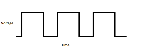
We’ve used square waves quite a bit when working with simple oscillators. They are easy to understand and easy to create, but how do they relate to the step response?
A square wave can be visualized as nothing more than a series of steps. First stepping up to the high voltage mark, then after some time stepping back down. Consider our example from last week, If instead of turning the power on and leaving it, you turned it on, waited for a period, then turned it back off. Repeating this process over and over would produce a square wave. It follows that we should be able to apply our step equation to the steps in a square wave.
A quick word about pulse width: One way square waves can be manipulated is by adjusting the “Duty Cycle.” This means changing the ratio of how long the signal is high versus how long the signal is low. To keep things simple today we will work with a 50% duty cycle meaning the signal will be high for the the same period it is low.
Frequency vs Period
When working with synthesizers you’ve probably heard signals described in terms of frequency. The frequency of a sound wave (Or any wave for that matter) is the number of times the signal cycles (goes up and back down) in a second and is expressed in Hz. For these calculations we need a slightly different descriptor for the speed of the waves. By taking the inverse of the frequency (1/f) we can find the period. The period describes the time in seconds that the wave takes to cycle. In a square wave with a 50% duty cycle we know that a step will take place twice every period (once up and once down). Further, these steps are evenly spaced. They take place at t=np and t=p(n+1/2) (Where n is any whole number).
Time Constant

In my last post I introduced the time constant. In an RC circuit the time constant is defined as the product of the resistance and capacitance (RC). It is used to determine the speed at which a capacitor will fully charge or discharge. Note the time constant is the same for both charging and discharging.
The graph above shows the relationship between the charging/discharging of a capacitor and the time constant in a 5V circuit. Since this is an exponential equation the capacitor will never fully charge or discharge (in theory) however for calculations we say that the capacitor is fully charged after 5 time steps. This charge would represent 99.3% of the maximum value. This means if you had a time constant of 0.2 the capacitor would take 1s to fully charge.
Filter Circuit

To illustrate how this all comes together lets have a look at the low pass filter circuit above. Let’s pass a square wave at 1Hz (50% duty cycle) into this circuit and see what happens. The first thing we need is our time constant for this circuit:

So if our time constant is 0.1 we know that it will take 0.5s for the capacitor to fully charge or discharge (5*0.1). With our frequency of 1Hz we know that the square wave will cycle every 1s (1/1). The steps in the square wave will occur every 0.5s (switching between stepping up and stepping down). This means every step will happen exactly when the capacitor reaches full or zero charge. So what does that look like?

Here we can see the charging and discharging cycles have turned our square wave into a sawtooth. This is only the beginning of what filters can do for us though.
The important question here is what would happen if we changed the frequency? If we doubled the frequency to 2Hz the period would become 0.5s (1/2). This means the steps would be occurring every 0.25s instead of every 0.5s. If we bring back the equation used in my last post we can see how much voltage would build across the capacitor in this time:

Here we can see that with a frequency of 2Hz the output voltage will only reach 4.59V before the input steps back down to 0V. This attenuation only gets worse as the frequency increases. At a frequency of 4Hz the peak voltage falls to 3.57V. At 8Hz you only see a peak voltage of 0.304V.
Note: This is a slight oversimplification, since we are shortening both the high and low periods. This means not only the charging but also the discharging state will be cut short. The capacitor will be unable to fully charge or discharge so the attenuated signal will stabilize at an offset from zero volts.
It is this attenuation that makes this a low pass filter. Low frequency signals (below a certain critical point) are able to pass at full amplitude while high frequency signals are attenuated or even eliminated from the output. We’ll explore filters further at a later date but this should give you some idea of the mechanisms which allow them to function.